


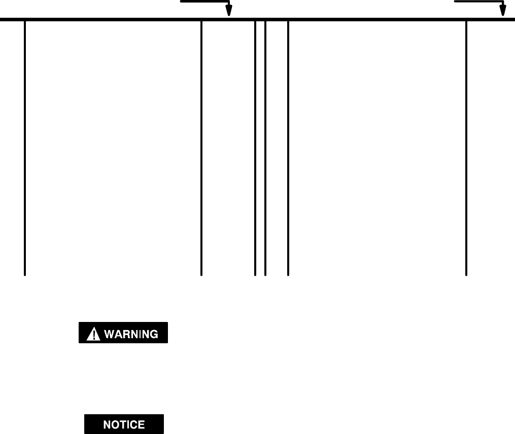
PART NUMBER FOR ORDERING PART NUMBER FOR ORDERING
M12
15
5
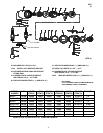
1 Inlet Adapter 44652–1
2 Air Diffuser 44649. . . . . . . . . . . . . . . . . . . . . . . . .
3 Roll Pin Y178–44. . . . . . . . . . . . . . . . . . . . . . . . . . . .
4 Throttle Lever (for –EU models see page 6) See table
5 Head See table. . . . . . . . . . . . . . . . . . . . . . . . . . . . . .
6 Lock Nut 44654. . . . . . . . . . . . . . . . . . . . . . . . . . .
7 Retaining Ring Y110–24. . . . . . . . . . . . . . . . . . . . . .
8 Valve 39382. . . . . . . . . . . . . . . . . . . . . . . . . . . . . .
9 ‘‘O” Ring Y325–6. . . . . . . . . . . . . . . . . . . . . . . . . . .
10 Spring 43244. . . . . . . . . . . . . . . . . . . . . . . . . . . . .
11 Washer 31389. . . . . . . . . . . . . . . . . . . . . . . . . . . .
12 Cover Screw 33920. . . . . . . . . . . . . . . . . . . . . . .
13 Screw Y8-463-C. . . . . . . . . . . . . . . . . . . . . . . . . . . . .
14 Washer Y48–6. . . . . . . . . . . . . . . . . . . . . . . . . . . .
15 Ball Bearing 42516. . . . . . . . . . . . . . . . . . . . . . . .
16 Wavy Spring 43150. . . . . . . . . . . . . . . . . . . . . . .
17 Rear End Plate 43185. . . . . . . . . . . . . . . . . . . . .
18 Rotor Blade (4 req’d) 41638. . . . . . . . . . . . . . . .
19 Rotor 44641. . . . . . . . . . . . . . . . . . . . . . . . . . . . . .
20 Spacer 43149. . . . . . . . . . . . . . . . . . . . . . . . . . . .
21 Roll Pin (2 req’d) Y178–1. . . . . . . . . . . . . . . . . . . .
22 Cylinder (includes item 21) 43152. . . . . . . . . . .
23 Front End Plate 43184. . . . . . . . . . . . . . . . . . . . .
24 Ball Bearing 42515. . . . . . . . . . . . . . . . . . . . . . . .
MOTOR ASSEMBLY (includes items 13 thru 24) 44645
25 Bevel Pinion See table. . . . . . . . . . . . . . . . . . . . . . . .
26 Housing See table. . . . . . . . . . . . . . . . . . . . . . . . . . .
27 Nut 43749. . . . . . . . . . . . . . . . . . . . . . . . . . . . . . .
28 Bevel Gear See table. . . . . . . . . . . . . . . . . . . . . . . . .
29 Ball Bearing 43750. . . . . . . . . . . . . . . . . . . . . . . .
30 Collet Shaft 44646. . . . . . . . . . . . . . . . . . . . . . . .
31 Drive Shaft 45171. . . . . . . . . . . . . . . . . . . . . . . . .
32 Lip Seal 41447. . . . . . . . . . . . . . . . . . . . . . . . . . .
33 Bearing Lock Nut 43909. . . . . . . . . . . . . . . . . . .
34 Collet See table. . . . . . . . . . . . . . . . . . . . . . . . . . . . .
35 Collet Nut 41751. . . . . . . . . . . . . . . . . . . . . . . . . .
OPTIONAL
Sanding Pad (2”) 44648. . . . . . . . . . . . . . . . . . . .
Sanding Pad (3”) 44647. . . . . . . . . . . . . . . . . . . .
Collet (1/8” cap.) 41750–1. . . . . . . . . . . . . . . . . . . .
Collet (3/16” cap.) 41750–2. . . . . . . . . . . . . . . . . . .
Collet (3 mm cap.) 41750–11. . . . . . . . . . . . . . . . . . .
Collet (6 mm cap.) 41750–12. . . . . . . . . . . . . . . . . . .
NOT SHOWN
Wrench (furnished with models
8479–1–( ) and 8479–2–( ) ) 37167. . . . . . . . . .
Wrench (furnished with all models) 39785. . . .
DISASSEMBLY/ASSEMBLY INSTRUCTIONS
Always wear eye protection when operating or perform-
ing maintenance on this tool.
Always turn off the air supply and disconnect the air
supply hose before installing, removing or adjusting any
accessory on this tool or before performing any mainte-
nance on this tool.
• Never apply excessive pressure by a holding device which
may cause distortion of a part.
• Apply pressure evenly to parts which have a press fit.
• Apply even pressure to the bearing race that will be press
fitted to the mating part.
• Use correct tools and fixtures when servicing this tool.
• Don’t damage ‘‘O” rings when servicing this tool.
• Use only genuine ARO replacement parts for this tool. When
ordering, specify part number, description, tool model num-
ber and serial number.
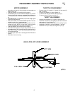
RIGHT–ANGLE DISASSEMBLY
– Remove lock nut (33). Remove shaft and components.
– Remove nut (27), gear (28) and bearing (29).
– Remove collet nut (35) and collet (34).
RIGHT–ANGLE ASSEMBLY
– Lubricate bearing (29) with ARO 33153 grease.
– Press bearing (29) onto shaft (30 or 31).
– Assemble gear (28) and nut (27) to shaft. Tighten to 15 – 18
ft lbs.
– Assemble seal (32) to lock nut (33). NOTE: Press seal to a
depth of .125” .015.
– Assemble lock nut (33), with seal (32), to shaft.
– Lubricate bearing in housing and gear with ARO 33153
grease.
– Assemble shaft and components to housing and secure
with lock nut (33).
– Assemble collet (34) to shaft and secure with collet nut (35).
MOTOR DISASSEMBLY
– Remove head section. Remove motor from housing.
– Remove gear (25) from rotor.
– Tap threaded end of rotor with a soft face hammer; motor will
come apart. NOTE: Bearings are light press fit in end plates
and press fit on rotor.
– NOTE: Screw (13) is assembled to rotor with a hard drying
adhesive and should not be disassembled unless it is nec-
essary to replace a worn part.