


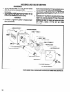
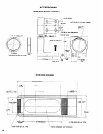
HOUSING AND VALVE SECTION
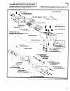
DISASSEMBLY
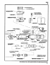
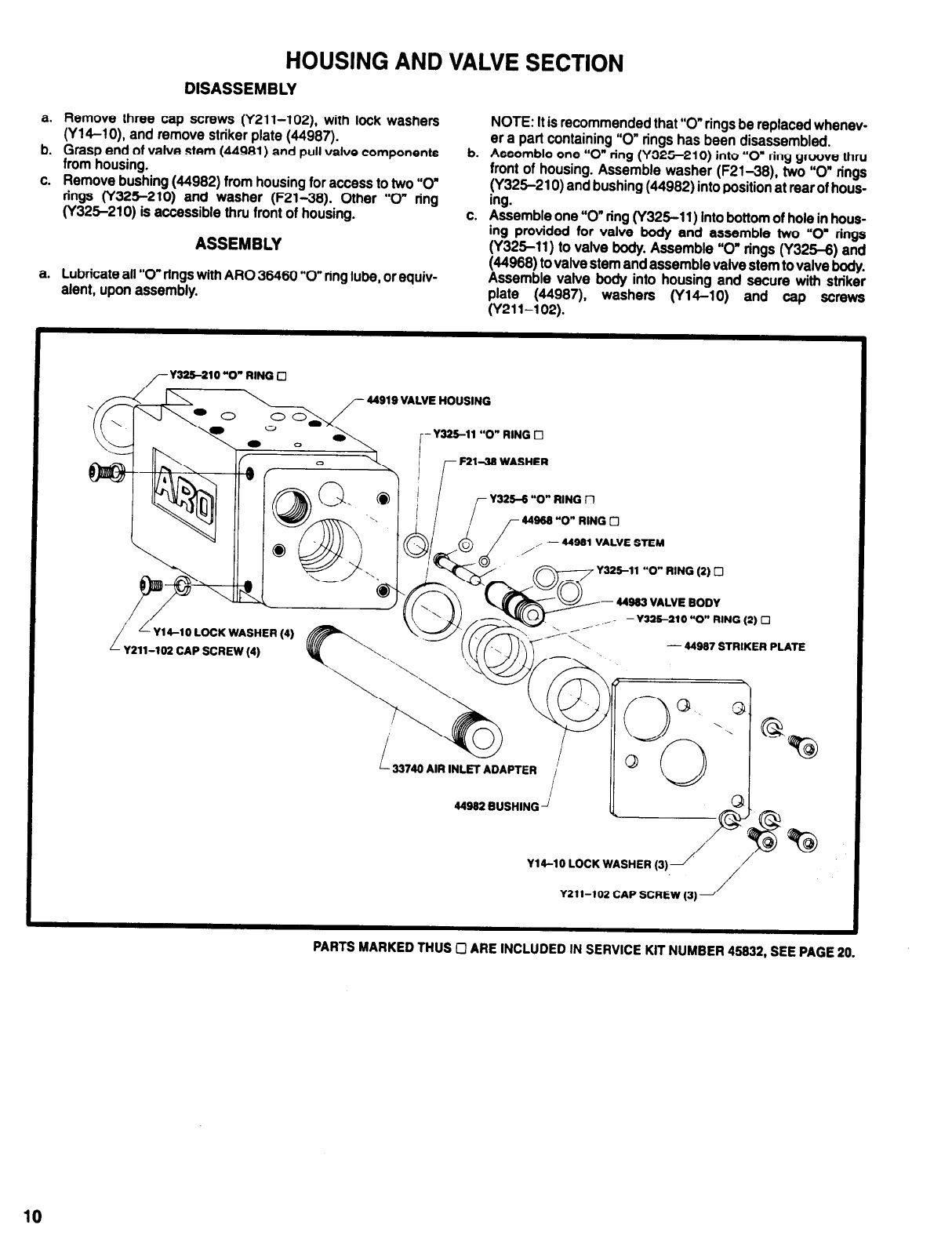
a. Remove three cap screws (Y211-102), with lock washers
b.
(Y14-10), and remove striker plate (44987).
Grasp end of valve stem (44981) and pull valve components
from housing.
c.
Remove bushing (44982) from housing for access to two “0”
rings (Y325-210) and washer (F21-38). Other “0” ring
(Y325-210) is accessible thru front of housing.
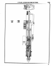
ASSEMBLY
NOTE: It is recommended that “0” rings be replaced whenev-
b.
era part containing “0” rings has been disassembled.
Assemble one “0” ring (Y325-210) into “0” ring groove thru
front of housing. Assemble washer (F21-38), two “0” rings
(Y325-210) and bushing (44982) into position at rear of hous-
ing.
c. Assemble one “0” ring (Y325-11) into bottom of hole in hous-
ing provided for valve body and assemble two “0” rings
(Y325-11) to valve body. Assemble “0” rings (Y325-8) and
a.
Lubricate all “0” rings with ARO 36480 “0” ring lube, or equiv-
(44938) to valve stem and assemble valve stem to valve body.
alent, upon assembly.
Assemble valve body into housing and secure with striker
plate (44987), washers (Y14-10) and cap screws
(Y211-102).
Y211-102 CAP SCREW (3)
10