


GEARING SECTION
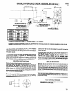
DISASSEMBLY
a. Secure motor housing (45168) in a suitable holding device
and remove chuck, bearing lock nut (45158) and bearing lock
screw (45159). Grasp end of spindle and pull gearing assem-
bly from housing.
NOTE: If gearing or motor assemblies do not slip freely from
housing, a rod or similar tool can be inserted thru rear of motor
housing and motor and gearing assemblies pushed out thru
front end of housing. Reasonable caution should be exer-
cised in doing this so as not to cause damage to nut (45189) or
threads of nut (44988). Push on rod, do not hammer. Motor
housing and head end of housing are pinned together at as-
sembly - do not remove.
b. Grasp ring gear housing in one hand and tap threaded end of
spindle with a soft face hammer; spindle and components will
loosen from ring gear housing.
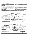
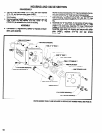
c. To remove gears from spindle: rotate snap ring so open por-
tion of ring aligns with one shaft. Remove shaft, releasing
gear. Repeat for removal of opposite shaft and gear.
ASSEMBLY
a. Assembly of gearing will be the reverse of disassembly proce-
dure. Pack bearings and lubricate gears liberally with ARO
33153 grease, or equivalent, when assembling. After assem-
bling gears and shafts to spindle, rotate open portion of snap
ring 60° from either shaft, securing shafts in spindle. Each
gearing assembly should contain approximately 1/4 oz. of
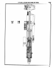
grease. Spindle assembly (45167) - pack bearings.
b. See “Motor Assembly” - paragraphs h, i and j.
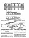
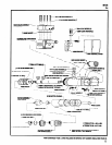
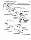
~- 44994-2 SHAFT (3)
45162 RING GEAR HOUSING
6