


10
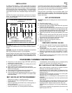
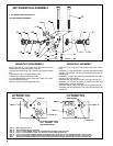
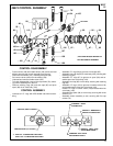
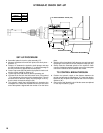
HYDRAULIC CHECK SET–UP
HYDRAULIC CHECK
‘‘X”
HYDRAULIC
CHECK
38922
38922–1
38922–2
STROKE
LENGTH
1”
2”
3”
CAP SCREW (28)
FEED RATE ADJUSTMENT
‘‘F” FEED CONTROL VALVE (103)
‘‘W”
‘‘Y”
SET–UP PROCEDURE
• Assemble hydraulic check to yoke assembly (27).
• Measure the distance from the drill point to the work piece –
distance ‘‘Y”.
• Distance ‘‘X” between the hydraulic check plunger and stop
pin (38) must be less than distance ‘‘Y” to prevent damage to
the drill point when it approaches the work piece.
• Loosen cap screw (28) and position the hydraulic check to ob-
tain the correct setting for distance ‘‘X”.
• Tighten cap screw (28) securely before operating unit.
• Increase the air flow thru the feed control valve (103) marked
‘‘F” by opening two full turns from the closed position. This will
allow the drill to advance rapidly until the plunger of the hy-
draulic check contacts the stop pin (38).
• The hydraulic check feed rate adjustment is located at the
nameplate end. Rotate the extended end until the slot at the
end of the spindle is aligned with the number 15 on the name
plate.
• Start the drill unit and the drill will advance at a rapid rate until
the plunger of the hydraulic check contacts the stop pin (38).
• Slowly rotate the extended spindle of the hydraulic check
counter–clockwise toward the number zero on the nameplate
until the drill advances at the desired rate of feed.
TO CONTROL BREAKTHROUGH
• Position the hydraulic check so the distance between the
plunger and the stop pin (38)(distance ‘‘X”) is less than the dis-
tance from the drill point to the opposite side of the work piece
(distance ‘‘W”).
• Set–up of the self–feed drill unit will be the same as explained
in ‘‘Set–Up Procedure”, page 3.