


M107
15
9
76*
104 105
94
95
96
f
97 f
98
97 f
106
107
108
109
94
95
f 96
112
99
100
101
103
f 102
110
111
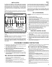
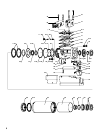
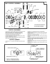
49674 CONTROL ASSEMBLY
* NOT INCLUDED IN ASSEMBLY
1/8–27 NPT
f INCLUDED IN 49596 SERVICE KIT.
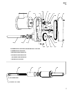
CONTROL DISASSEMBLY
_ Control valves (100) and needle valves (103) can be serviced
without removing the control assembly from the tool.
_ Remove three screws (112), releasing face plate (99).
_ Pull control valves (100) from valve body (106).
_ Unthread and remove needle valves (103).
_ To further disassemble, remove five cap screws (76), releas-
ing control assembly from the tool.
_ Remove retaining rings (94) and end caps (95) and push
spool (98) out of valve body (106).
CONTROL ASSEMBLY
_ Lubricate all ‘‘O” rings with ARO 36460 lube when assem-
bling.
_ Assemble ‘‘O” rings (96) to grooves in end caps (95).
_ Assemble one end cap (95) to valve body (106), securing with
retaining ring (94).
_ Assemble ‘‘O” rings (97) to grooves in spool (98) and as-
semble spool into valve body (106).
_ Assemble end cap (95) to valve body, securing with retaining
ring (94).
_ Assemble ‘‘O” rings (102) to grooves in needle valves (103)
and thread needle valves into valve body (106).
_ Grease ‘‘O” rings on control valves (100) and assemble into
valve body (106).
_ Assemble face plate (99) to valve body, securing with three
screws (112).
_ Assemble control assembly to tool, securing with five cap
screws (76).
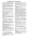
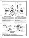
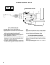
FORWARD / START
PUSHBUTTON
RETRACT / EMERGENCY
RETRACT PUSHBUTTON
RETRACT FEED RATE
ADJUSTMENT KNOB Q
FORWARD FEED RATE
ADJUSTMENT KNOB Q
EXHAUST, FEED CYLINDER
MAIN AIR INLET (1/8–27 N.P.T.)
Q TURN ‘‘IN” TO DECREASE FEED RATE.
TURN ‘‘OUT” TO INCREASE FEED RATE.