


26
MAINTENANCE SECTION
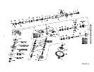
4. Insert the Throttle Valve Spring (6), small end first,
into the Handle.
The Inlet Bushing (4) has an interference thread.
Apply a light film of the recommended oil to the
threads before assembly.
5. Clean the face of Inlet Bushing (4) and the Inlet
Bushing Screen (5) with a clean, suitable, cleaning
solution and allow to dry. Insert the parts into the end
of the Throttle Handle. Tighten the Inlet Bushing to
125 ± 26 ft–lb (170 ± 35 Nm) torque.
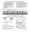
Assembly of the Angle Head
For GRG15A or GRG15M Models:
1. Install the Lower Arbor Spring Washer (51) onto the
Depressed Center Wheel Arbor (60).
2. Press the Arbor Lower Bearing (50) onto the
Depressed Center Wheel Arbor until it contacts the
Lower Arbor Spring Washer.
If the Bevel Gear (40) is worn or broken, replace
both the Bevel Gear and the Pinion as they are a
matched set and cannot be matched with other
Pinions.
3. Grasp the flats of the Depressed Center Wheel Arbor
in leather–covered or copper–covered vise jaws, arbor
bearing end up. Install the Bevel Gear on the Arbor.
4. Install the Bevel Gear Spacer (49).
5. Clean the threads on the Arbor; apply a film of thread
locking compound to the threads. Screw the Bevel
Gear Nut (48) onto the Arbor and tighten to 8.5 to
11.5 ft–lb (11.5 to 15.5 Nm) torque. Remove the
Arbor from the vise.
6. Grasp the Angle Arbor Housing (43) in
leather–covered or copper–covered vise jaws, angle
head up. Install the Upper Bearing Spring Washer
(46) and Upper Arbor Bearing (47).
7. If replacement of the Mounting Plate Pin (45) is
necessary, press a new pin into the Angle Arbor
Housing.
8. Install the assembled Depressed Center Wheel Arbor
into the Angle Arbor Housing.
9. Place the Depressed Center Wheel Guard (59) in
position on the Angle Arbor Housing, making sure the
Mounting Plate Pin aligns with the pin hole in the
guard.
10. Install the Screw Lock Washers (53) and Guard
Screws (54). Tighten to 7.5 to 8 ft–lb (10 to 11 Nm)
torque.
11. Slide the Autobalancer Assembly (61), rectangular
hub side leading, onto the Arbor.
12. To mount the wheel on the tool, proceed as follows:
For Type 27 and Type 28 Plain Hole Wheels:
a. Thread the Depressed Center Wheel Flange (66 or
68) onto the Arbor against the Autobalancer
Assembly.
b. Slide the wheel onto the Arbor against the
Depressed Center Wheel Flange.
c. Thread the Depressed Center Wheel Nut onto the
Arbor against the wheel and tighten the Nut using
the Depressed Center Wheel Spanner Wrench
(Part No. D32–26). Tighten the Nut only enough
to drive the wheel and prevent slippage.
d. Using a hex wrench, install the Wheel Retaining
Screw (65) in the end of the Arbor.
For Type 27 Mounted Wheels:
a. Install two Depressed Center Wheel Spacers (63)
on the Arbor against the Autobalancer Assembly.
b. Thread the wheel onto the Arbor.
c. Using the hex wrench, install the Wheel Retaining
Screw (65) in the end of the Arbor.
For Type 28 Mounted Wheels:
a. Install one Depressed Center Wheel Spacer (63)
on the Arbor against the Autobalancer Assembly.
b. Thread the wheel onto the Arbor.
c. Using the hex wrench, install the Wheel Retaining
Screw (65) in the end of the Arbor.
13. Insert a 5” (127 mm) long 3/16” hex wrench into the
elongated slot in the end of the Dead Handle (70) and
into the hex recess in the screw head.
14. Position the Handle against the Angle Arbor Housing
(43) and thread the screw into the Housing. The
Handle can be attached at either of two positions 180
degrees apart. Select the desired position and tighten
the screw to 18 ft–lb. (24.4 Nm) torque.
15. Inject approximately 5 cc of IRAX No. 68 –1LB
Grease into each Grease Fitting (44).
For GRP15A, GRS15A Models:
1. Install the Lower Arbor Spring Washer (51) onto the
Sander Arbor (55). Press the Arbor Lower Bearing
(50) onto the Arbor until it contacts the Lower Arbor
Spring Washer.
If the Bevel Gear (40) is worn or broken, replace
both the Bevel Gear and the Pinion as they are a
matched set and cannot be matched with other
Pinions.
2. Grasp the flats of the Arbor in leather–covered or
copper–covered vise jaws, arbor bearing end up.
Install the Bevel Gear on the Arbor.
3. Install the Bevel Gear Spacer (49).