


PP20A-XXX-XXX (en) Page 3 of 12
small or restrictive, which will inhibit material flow. The
outlet material volume is governed not only by the air
supply, but also by the material volume available at the
inlet.
Air supply provided should be filtered to provide clean,
dry air. A filter capable of filtering out particles larger
than 40 microns should be used on the air supply. There
is no lubrication required other than the “O” ring lubricant
which is applied during assembly or repair.
If lubricated air is present, make sure that it is compatible
with the Nitrile “O” rings in the air motor section of the
pump.
NOTE: When using air for powder uidization, make sure
it is ltered and very dry.
INSTALLATION
WARNING
THE PUMPING SYSTEM MUST BE GROUND-
ED TO PREVENT STATIC DISCHARGE. THIS INCLUDES
THE PUMP AND ALL INPUT AND OUTPUT SUPPLY
LINES AND RELATED SYSTEM DEVICES AND ACCESSO-
RIES. FAILURE TO DO SO CAN RESULT IN EXPLOSION
AND SERIOUS PERSONAL INJURY.
SYSTEM GROUNDING
Consult local building codes and electrical codes for
speci c requirements.
Must comply with all applicable Local and National
codes for such applications.
Grounding is accomplished through the ground lug
and strap provided on the pump. Keep the grounding
strap as short as possible.
Safe operating conditions are the responsibility of the
installer and operator.
Secure the diaphragm pump legs to a suitable surface
to avoid damage by excessive vibration.
OPERATING INSTRUCTIONS
START-UP
NOTE: PRIOR TO START-UP, MAKE SURE THE GROUNDING
INSTRUCTIONS WERE FOLLOWED.
Connect air supply to (263) main air supply control valve
(30 - 40 p.s.i. / 2.1 - 2.8 bar).
Turn the air on.
Attach air (or gas) to (248) lter / regulator. CAUTION: Do
not apply excessive Fluidization Gas* Pressure (refer to
note under “General Description”).
At (248), turn on air (or inert gas) supply. There will be a
3 to 8 second time delay, during which the pump will be
fluidizing any powder left in the pump from an earlier
dispense. This time delay will occur on all start-ups.
OPERATION AND ADJUSTMENT
NOTE: Powder type materials can vary in ow-ability and the
same settings may not work universally. Factors such as den-
sity and humidity can require changing the mixture of ow
rate and uidization air and some experimenting should be
expected.
IMPORTANT: DO NOT TURN FILTER / REGULATOR (248) OFF.
Positive air (or gas) pressure must be supplied to the lter /
regulator to allow the pump to function. Powder will accu-
mulate in the uid caps if the pump is not allowed to expel
excess material before the pump shuts down. Restart can
1.
2.
3.
4
.
GENERAL DESCRIPTION
The ARO diaphragm pump o ers high volume delivery even
at low air pressure and a broad range of material compat-
ibility options available. Refer to the model and option chart.
ARO pumps feature stall resistant design, modular air motor
/ uid sections.
Air operated double diaphragm pumps utilize a pressure dif-
ferential in the air chambers to alternately create suction and
positive fluid pressure in the fluid chambers, valve checks
insure a positive ow of uid.
This diaphragm pump was developed to address the unique
problems associated with pumping dry powders, which can
“pack out” inside the pump fluid chambers, if not kept in a
semi- uid state.
This system incorporates the use of special valves to intro-
duce air or inert gas* into the uid chambers simultaneously
to a pumping cycle in a timed sequence which keeps the
powder in a uidized state during the transfer process.
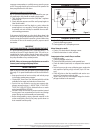
THEORY OF OPERATION
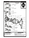
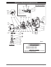
The main air distribution valve (252) is a double pilot actu-
ated four-way valve. It is a slave to the pump major air valve.
The distribution valve recognizes the signal from two pump
major air valve (259) ports (air dumps). These signals are con-
verted into alternating output pressure distributions, which
are injected into the uid chambers during the pumping cy-
cle to uidize the powder as the diaphragm moves through
the discharge stroke.
The ow of air supplied to the uid chamber is controlled by
the (248) filter / regulator. Under normal operating condi-
tions, this is the primary control.
When air is supplied to the filter / regulator (248), the dis-
tribution valve directs the ow of air into the uid chamber
that will dispense rst for 3 to 8 seconds. The time delay then
supplies the start signal to open the main pump air supply
valve. When the pump diaphragm reaches the end of the
discharge stroke, it reverses direction. The distribution valve
then shifts and shuts off the fluidizing air to the first fluid
chamber as it applies a burst of air to the second uid cham-
ber and uidizes the powder in the second chamber.
The air induction ori ce (76) increases the air velocity prior
to injection point because of the ori ce and it prevents clog-
ging of the injector feed line.
NOTE: The restart valve (258) is a bleed valve which will stop
the pump and then restart the pump by re-initiating the time
delay cycle.
*NOTE: Use of other gases: Using only a gas to operate a 2”
pump can be rather expensive because of the high volume
needed. Separate air / gas inputs allow the uidizing feature
of this pump to utilize special inert gas, such as Nitrogen or
Argon (air), if necessary and still allow use of standard com-
pressed shop air for the pumping function.
The ability to introduce special gas also means special ma-
terials could be injected through the fluidization lines. Ap-
plications may include such materials as colorants, foaming
agents, additives, neutralizers, etc.
AIR AND LUBE REQUIREMENTS
WARNING
EXCESSIVE AIR PRESSURE. Can cause pump
damage, personal injury or property damage. The
pump air supply must be limited to 50 p.s.i.g. (3.4 bar)
maximum inlet air pressure.
The air supply line or hose to the pump should be ad-
equately sized to carry a sufficient volume of air to the
pump. The material inlet supply tubing should not be too