


Intel
®
Server Board S5000PAL User’s Guide xvii
List of Figures
Figure 1. Intel
®
Server Board S5000PAL.................................................................................. 1
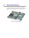
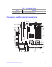
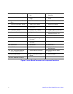
Figure 2. Server Board Connector and Component Locations ................................................. 4
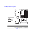
Figure 3. BIOS Select Jumper................................................................................................... 5
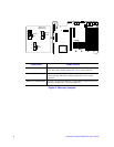
Figure 4. Recovery Jumpers ..................................................................................................... 6
Figure 5. Light Guided Diagnostic LEDs ................................................................................... 7
Figure 6. Back Panel Connectors.............................................................................................. 8
Figure 7. DIMM Configuration Diagram................................................................................... 11
Figure 8. Four DIMM Configuration Example.......................................................................... 12
Figure 9. Clear Password Jumper........................................................................................... 19
Figure 10. Clear CMOS Jumper.............................................................................................. 20
Figure 11. Installing the Memory............................................................................................. 22
Figure 12. ILifting the Processor Socket Handle..................................................................... 24
Figure 13. Installing the Processor.......................................................................................... 24
Figure 14. Removing the Socket Cover .................................................................................. 25
Figure 15. Installing the Heat Sink .......................................................................................... 26
Figure 16. Replacing the Backup Battery................................................................................ 29
Figure 17. Diagnostic LED Placement Diagram...................................................................... 54