


8
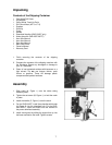
Adjusting the Head Height
To facilitate shipping, the Drill Press is packed with the
head adjusted down on the column. The head assembly
should be moved to the top of the column before drilling
operation starts.
The head assembly is very heavy.
Use caution when adjusting the head and make sure
it is supported by the table or locked in place. Failure
to comply may cause damage to property and/or
personal injury!
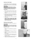
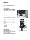
1. Unlock the table by loosening the handle (A, Figure
3)
2. Lower the table until there is room to place a block of
wood between the table and the head assembly
(Figure 4).
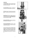
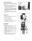
3. Loosen two nuts (A, Figure 5) on the head assembly.
4. Raise the head by raising the table. The head is at
the correct height when the top of the head is just
below the column cap (B, Figure 5).
5. Tighten the two nuts (A, Figure 5) on the head
assembly firmly.
6. To lower the head, reverse the steps above. Do not
loosen the head assembly bolts without
supporting the head. This may cause the head to
slip on the column and may cause damage to the
machine or personal injury.
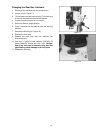
Adjusting the Rack Assembly
After the table has been adjusted, the rack assembly will
need to be raised.
The table must be locked when
raising the rack. Failure to lock the table may cause
the assembly to drop on the column, causing
damage to the machine.
1. Make sure both head assembly nuts (A, Figure 5)
are tight.
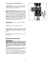
2. Loosen the hex socket cap screw (C, Figure 6) on
the upper rack ring.
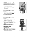
3. Loosen two set screws on the bottom rack ring (D,
Figure 7).
4. Raise the rack assembly by turning the table raising
handle clockwise.
5. The rack assembly is at its full height when the top
rack ring is just below the head assembly (as
illustrated in Figure 6).
6. Tighten the hex socket cap screw on the top rack
ring and two set screws on the lower rack ring.
Figure 3
Figure 4
Figure 5
Figure 6