


8
operating manual)
(on the last pages of this
operating manual)
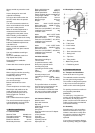
A.1.: Ripping
A.2.: Ripping of narrow stock
A.3.: Crosscutting on rip fence
A.4.: Mitre cutting
A.5.: Ripping of big board
7. Setup and adjustments
General note:
Setup and adjustment work may
only be carried out after the
machine is protected against
accidental starting by pulling the
mains plug.
7.1 Changing sawblade
The sawblade has to meet the
technical specification.
Use only sawblades according to
EN 847-1
Check sawblade for flaws (cracks,
broken teeth, bending) before
installation. Do not use faulty
sawblades.
The sawblade teeth must point in
cutting direction (down)
Always wear suitable gloves when
handling sawblades.
WARNING:
When installing or changing saw
blade, always disconnect saw from
power source, unplug!
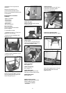
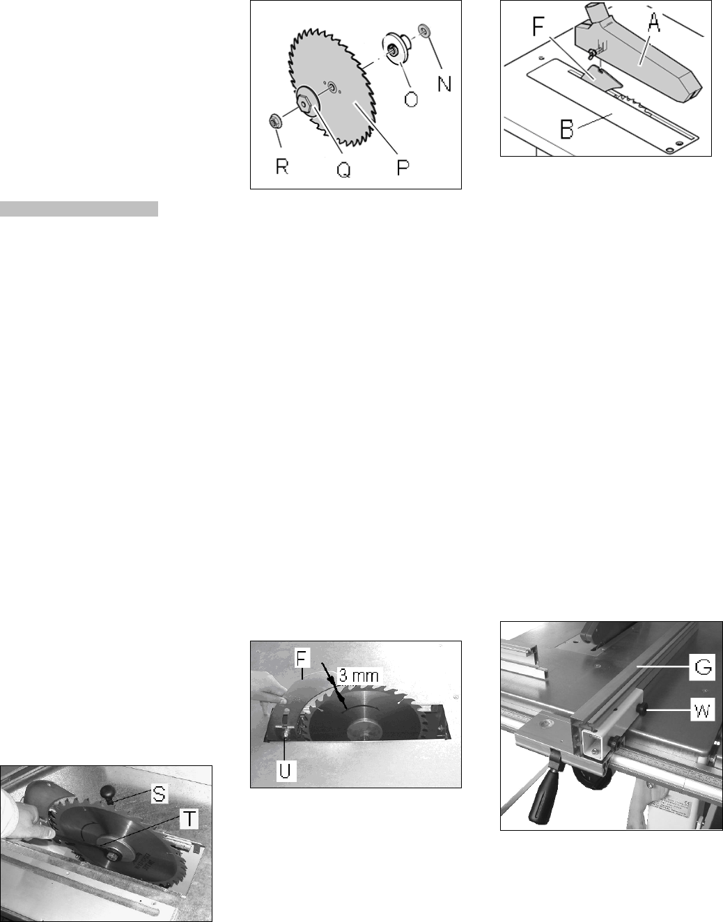
Remove the saw guard (A, Fig 1))
and table insert (B).
Raise sawblade fully.
Loosen the arbor nut while stopping
the arbor against rotation with the
supplied tools (S, T, Fig 15)
Fig 15
Attention: left hand thread.
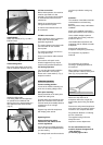
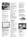
Remove the arbor nut (R, Fig 16 and
flange (Q).
Fig 16
Place saw blade(P) on arbor shaft
making sure teeth point down at the
front of the saw.
Reinstall flange and arbor nut and
securely tighten.
Order for installation:
-adjusting washer (N)
-centring flange (O)
-saw blade (P)
-tightening flange (Q)
-left handed nut (R)
Reinstall the table insert and the saw
guard.
7.2 Mounting the raving knife
The supplied raving knife must
always be used.
Disconnect saw from power source,
unplug!
The raving knife (F, Fig 17) is
clamped with 1 nut (U).
Fig 17
Adjust the space between sawblade
teeth and raving knife to be 2 to
5mm.
Well tighten the locking nut (U).
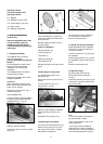
7.3 Mounting the saw guard
The saw guard must always be used.
Attach the saw guard (A, Fig 18) to
the raving knife (F) with 1 carriage
bolt, washer and wing nut
Fig 18
The saw guard must be lowered to
the work piece to minimise the
amount of exposed teeth.
7.4 Rising and tilting of sawblade
Setup adjustments of the sawblade
shall never be performed when the
machine is running.
Use the front handle (I, Fig 1)to raise
the sawblade.
Use the tilting handle (H, Fig 1) to tilt
the sawblade. Tighten knob to lock in
place.
Start the machine with care.
7.5 Rip fence setup
Rip fence setup shall never be
performed when the machine is
running.
Use 2 bots and wing nuts (W, Fig 19)
to attach the aluminium profile (G) to
the rip fence body
Fig 19
Note:
The rip fence profile can be placed
flat and adjusted in length.
-Use in upright position (Fig 19) for
cutting wide stock:
-The cutting of small workpieces
(width less than 120mm) and tilted
cuts shall only be performed with the
rip fence profile placed flat (Fig 20).