


10
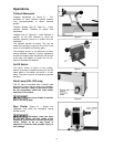
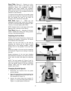
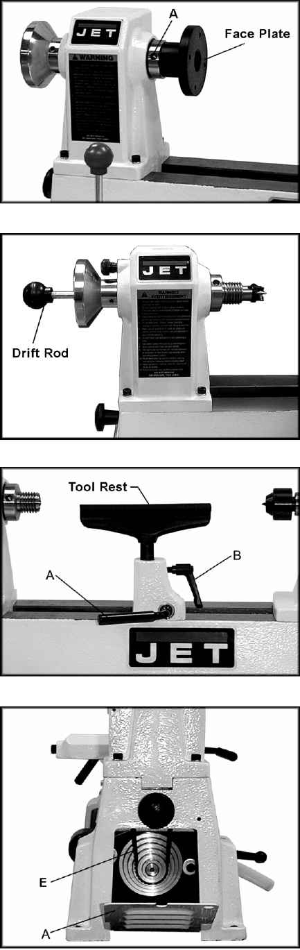
Face Plate (Figure 6) – Screws on to the
headstock and is used in face plate turning
operations. Mount your workpiece onto the
faceplate with brass screws (not provided).
Make sure the screws are not so long that they
will enter the area of the workpiece where the
material is to be removed.
To remove the face plate from the spindle, place
the drift rod into hole (A, Figure 6) and let the
drift rod contact the bed of the lathe for
leverage. Then unscrew the face plate.
Drift Rod (Figure 7) – Slides into the
headstock to tap the spur center free. Stored in
the hole in the base below the headstock (JML-
1014I) or in the tool caddy (JWL-1220).
NOTE: Always hold on to the spur center while
tapping it free, to prevent it from falling.
Tool Rest (Figure 8) – Attaches to the bed.
Used to steady the cutting tool during spindle
turning or face plate operations.
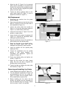
Adjusting the Tool Rest
Position the tool rest (Figure 8) as close to the
workpiece as possible. It should be 1/8” above
the centerline of the workpiece.
Position the tool rest base on the bed by
releasing the locking rod (A, Figure 8) and
sliding base to the desired position. Tighten
locking rod to fix the position of the tool rest
base.
Adjust the height of the tool rest by loosening
the handle (B, Figure 8) and raising or lowering
tool rest.
Should adjustment of the tool rest clamping
device become necessary, turn off the machine,
reach under the bed, and adjust the clamping
nut.
NOTE: The lock handles (B, Figure 2 and B,
Figure 8 for example) are adjustable. Simply pull
up on the handle, rotate it on the pin, and then
release. Make sure the handle seats itself
properly upon the pin.
Changing Spindle Speeds
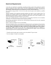
1. Disconnect the machine from the power
source (unplug).
2. Open the access doors at the left side of the
base (A, Figure 9) and at the back side of
the headstock (B, Figure 10).
3. Loosen the motor plate lock handle (C,
Figure 11). Lift up the motor plate handle (D,
Figure 11) to take tension off the belt.
Figure 6
Figure 7
Figure 8
Figure 9