


9
Figure 6
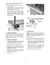
6.7 XACTA Fence
Screw knob into threaded handle on fence, as
shown in Figure 7.
Figure 7
The lock lever has three functional positions as
shown in Figure 8:
Figure 8
1. Upright position permits mounting and removal
of fence from saw.
2. Unlock position permits easy fence positioning.
3. Lower position locks fence to guide tube. The
cam handle should be pushed down firmly
against the pin.
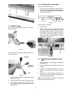
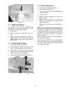
6.8 Leveling fence to saw table
Place fence on table and lock it.
1. View the fence from left side of saw (Figure 9).
Look for the space between the table and the
fence bottom to be equal along entire length of
fence (A, B, Figure 9).
Figure 9
If adjustment is necessary:
2. Unlock fence.
3. Raise or lower two nylon adjustment screws
(D, Figure 10) the same number of turns until
the space between bottom of fence and table
is the same. Care must be taken to raise or
lower fence on each side equally or the fence
may not be 90° to the table after the height
adjustment is performed.
Figure 10
6.9 Adjusting fence parallel to miter
slot
1. Place fence next to outside edge of right miter
slot and lock it.
2. Fence should be even with miter slot from front
to back.
3. If fence is not even along length of miter slot,
unlock fence, remove it and turn it upside
down.
4. Adjust one of two setscrews (A, Figure 11)
until fence is even with miter slot edge along
its entire length when locked.
Note: You may need to re-adjust the clamping
pressure after aligning the fence.