


4/29/03
Manual V-16, V-24, VH-24, V-40 & VH-40 11 – Section I
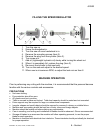
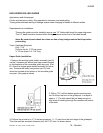
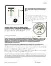
An analysis of the work to be performed should be made and the proper
blade selected. The blade should always be inspected before installing
on the machine. Things to look for should be the smoothness on the
sides and back edge of the weld, look for any missing teeth, or
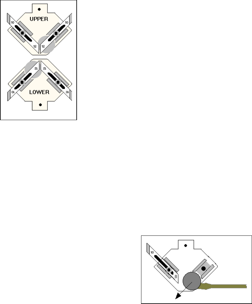
impacted chips. The blade guides may now be selected and inserted
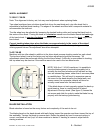
into both the upper and lower guide holders. Proper adjustment of these
guides takes place when they form a complete “V” shape (see graphic
below) and support the blade equally on each side. A couple of
thousands on each side of the blade will provide the running clearance
and support for contour sawing.
Note: Blade guides should be cleaned of chips each blade
change or more frequently if required.
BLADE GUIDES
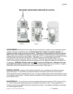
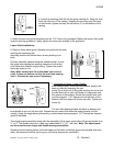
The back end roller that supports the back of the blade on each guide holder contains a hardened cap
over a set of ball bearings. This should be checked periodically for free movement so it is allowed to
rotate freely as the back of the blade comes in contact with the face of this roller. Noticeable friction in
this assembly indicates it should be replaced. This can be done by removing the right hand guide
insert, moving the left hand guide up away from the bearing face. Loosen the setscrew on the bottom
of the guide holder and sliding the old bearing and shaft out and a new one in. Tighten the setscrew
and re-adjust the guides. See graphic below.
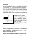
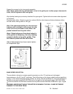
The “V” type solid blade guides and holder assemblies as furnished standard with the machine are
recommended for the majority of cutting applications. This is true for the cutting of materials at blade
speeds in the low range.
If the machine is operated in the high range, it should be operated with the high-speed roller guides,
supplied with this machine, installed.
NOTE: If machine is operated in excess of above, abnormal blade wear and breakage may
occur, due to the increased heat developed with the standard solid guides.