


4/29/03
Manual V-16, V-24, VH-24, V-40 & VH-40 23 – Section I
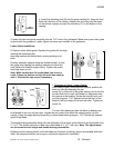
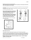
After welding loosen the pressure clamps (7 fig. 1) and set the jaws to the wide annealing position by
turning the upsetting pressure switch (2 fig. 1) counter clockwise. Re-clamp the blade so that the weld
is in the center between the jaws. Operate the annealing switch (8 fig.1) until the weld becomes dark
cherry red. This will take from 1 to 5 seconds depending on the blade width. Allow blade to cool until
the blade returns to a dark color. Repeat this process at least three times. Some brittle alloys require
more annealing than the standard carbon blades.
Note: It is difficult to weld and anneal bi-metal blades due to the make up of this type of blade. It
will take some practice to successfully achieve a suitable weld.
WARNING: BLADE WILL BE HOT!
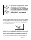
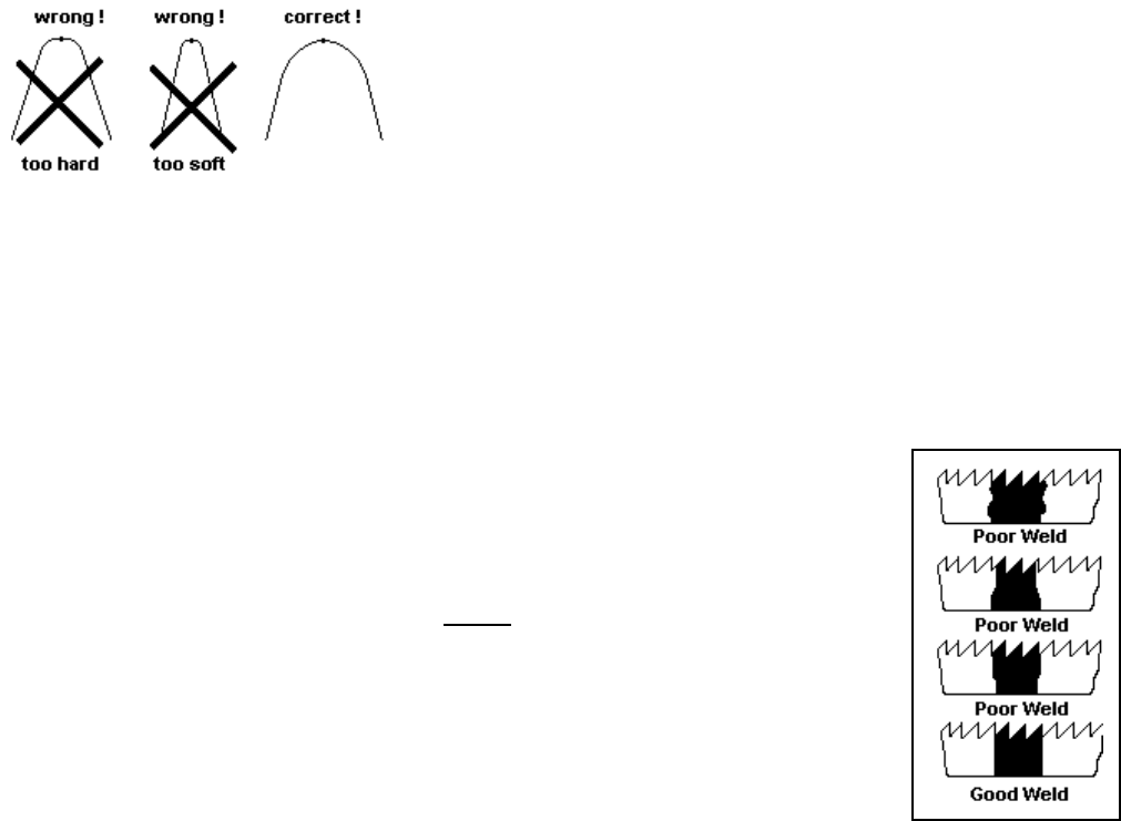
After annealing bend test your weld:
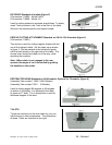
6. RE-FINISHING THE WELD
Welding burr (flash) can be removed by finishing with a grinding wheel above the welder. Grind in a
longitudinal direction, other wise transverse fractures may occur. The proper finish of the blade after
grinding, a tempered steel-blue coloring.
Note: Do not over grind, into the blade facing. Remove any burr on the back edge of the blade
.
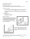
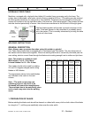
WELDER LAYOUT AND CONTROLS
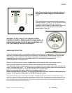
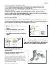
7. WELDER MAINTENANCE
If the clamping areas of the jaws are dirty or deformed so they so not clamp
evenly, good welds cannot be made. Any dirt or metallic debris must be
removed from the jaws. The jaws should never
be filed. It should only be
polished with a proper cleaning material and if absolutely necessary polished
with fine emery cloth held on a flat piece of bar stock. The uniformity of current
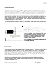
flow and contact pressure can be checked by putting the welder in the
annealing position and clamping a piece of blade stock with out a weld in the
jaws. When the annealing switch is turned to the heating position the blade
should heat uniformly over its entire width. (See fig. 2) If the heating is not
uniform the clamping devices should be checked for dirt or misalignment.
figure 2
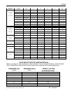
8. POOR WELDS / TROUBLE SHOOTING
If the welded seam contains holes, the upsetting pressure should be increased, the welding current
reduced or both settings changed. We must emphasize once again that proper welds cannot be
made if the blade ends are not cut square, and properly cleaned. Welding of blades may take
practice, do not be discouraged if your welds are not perfect at first.
Avoid overlapping when welding thin blades. If welder does not give suitable weld, check in coming
voltage to the machine. If voltage is low, use next blade size setting. Example: 220 volt machine,
incoming voltage is 208 volt, to weld 1/2” blade use 5/8” settings.