


4/29/03
Manual V-16, V-24, VH-24, V-40 & VH-40 10 – Section I
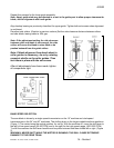
BLADE TENSIONING
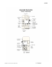
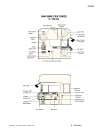
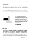
The blade indicator is located inside the upper wheel compartment, on the lower left side of the idle
wheel. (See machine features graphic) The indicator has an arrow mounted on the horizontal plane,
with a corresponding scale for blade tensioning. The scale has two legends, one reads inches from 0 -
1”, the second reads mm 0 - 25 mm. This allows tensioning either standard or metric blade widths.
With out tension on the blade, the indicator should read zero. As tension is applied to the blade the
needle will move accordingly, and should be tightened until the correct blade width is indicated on this
gauge. Example: Installing a 1/2” blade on the machine, tighten the handwheel until the indicator’s
arrow is pointing to the 1/2” mark on the scale. Before starting the machine check the blades tracking
by hand as described in an earlier section.
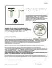
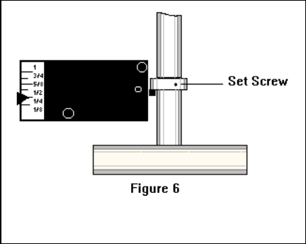
This indicator has been calibrated at the factory. If recalibration is ever needed follow the steps below.
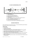
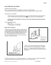
Using a blade tension gauge, (many times the
company that you purchase blades from can furnish
you with this gauge) tension the blade to the proper
PSI. The PSI will very from blade types (carbon, Bi-
metal) and blade widths. This information can be
obtained from your blade supplier. When proper
tension is achieved, loosen the setscrew in the collar
on the tensioning wheel shaft. (See figure 6) Adjust
this collar up or down on the shaft until the arrow is
pointing to the corresponding blade width. on the
indicator. Tighten setscrew.
Note: It is better to over tension the blade than to
run it under tensioned.
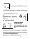
BLADE GUIDES
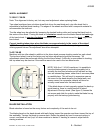
Your machine has come equipped with a set of interchangeable “V” type blade guides. A set of
guides consist of two each left hand and two each right hand guide inserts. The standard
guides furnished are 10 / 12 mm guides. Other sizes are optional, and can be purchased
separately, or as a five piece set. The five-piece set includes 3 / 4 mm (1/8 - 1/4”) 6 / 8 mm
(5/16 - 3/8”) 10 / 12 mm (standard set 1/2 - 5/8”) 16 / 20 mm (3/4”) and 25 / 32 mm (1”) The
blade width will dictate the size blade guide to be used.
Note: Never use blades larger than the rated capacity of the machine. Never use blades
narrower than guide insert. Damage will occur to guide insert and blade. Blade insert must
correspond with blade width.