


4/29/03
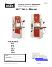
Manual V-16, V-24, VH-24, V-40 & VH-40 9 – Section I
WHEEL ALIGNMENT
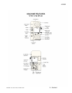
V-16 & V / VH-24
Note: This alignment is factory set, but may need adjustment when replacing blade.
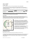
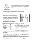
Two wheel machines have a bottom wheel that drives the saw blade and a top idle wheel that is
adjustable to facilitate blade tracking. The edges of the wheels are fitted with a composite material to
accommodate the tooth set.
The idle wheel may be adjusted by loosening the knurled locking collar and turning the black knob in
the center of the wheel. Turning the knob in a clockwise
manner runs the blade toward the back edge
of the band wheel. A counter clockwise
movement will move the blade toward the front edge of the
band wheel.
Correct tracking takes place when the blade runs approximately in the center of the wheel.
NOTE: The main casting with adjusting screws have been preset at the factory during assembly
utilizing special fixtures. No adjustment should be attempted.
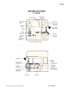
V-40 / VH-40
Machines with two idle wheels in addition to the drive wheel possess tracking control on each wheel.
The top band wheel is set at the factory and no future adjustment should be necessary. *All
adjustments should be performed utilizing the third band wheel. If difficulty is encountered in tracking,
the top wheel may be reset as if the machine were to be used in the two wheel mode.
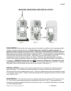
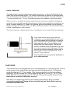
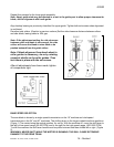
NOTE: With the V / VH-40 machines, it is possible to
have the blade appear to be tracking properly but in
actuality the two band wheels can be adjusted so they
form an intersecting planes, rather than a common plane
or parallel plane. This will result in excessive wear on
the crown on the band wheel by the blade teeth, and
severe cases, the composite material will shred or
actually come loose from the band wheel.
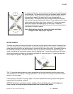
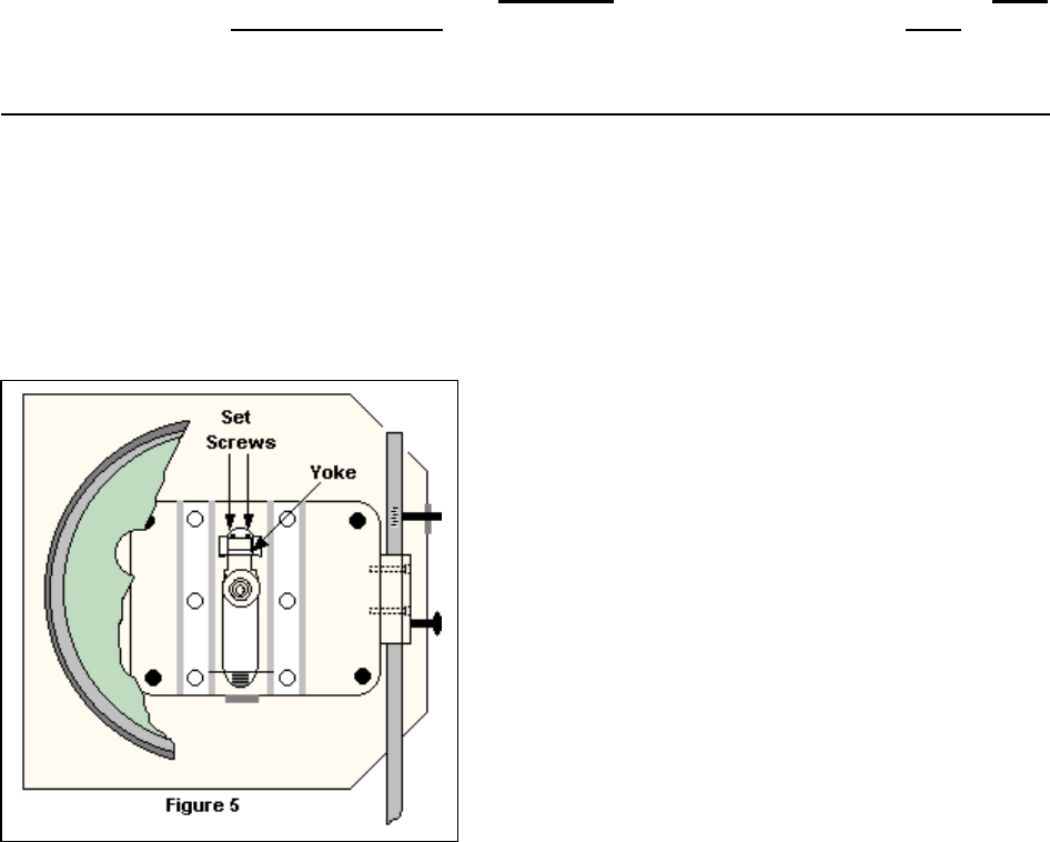
*If the blade does not track properly against the back up
guide bearing, there is a small amount of lateral
adjustment in the top wheel. (See figure 5) Loosen the
set screws and slide the yoke to make the blade line up
properly with the backup guide bearing.
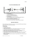
BLADE INSTALLATION
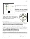
Blade selection is based on the many factors and complexity of the work to be cut.
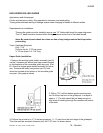
The blade placed on the band wheels with teeth facing toward the operator and down toward the top of
the worktable. Tension the blade to remove slack. Rotate the wheels by hand to ensure tracking is
correct, and blade will not “pop” off when machine is started. If tracking is incorrect, adjust before
starting machine.