


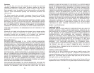
FUNCTIONAL DESCRIPTION
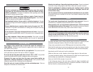
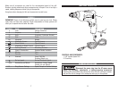
CONTROLS AND COMPONENTS:
1. 3/8" Variable Speed Drill
2. Chuck Key
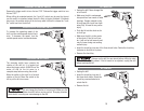
OPERATING INSTRUCTIONS
Disconnect the power plug from the AC power source
before any assembly, adjustments, or adding/removing accessories.
Following this preventative step reduces the risk of the drill coming on acciden-
tally and the risk of damage to the workpiece and injury to the operator.
8
7
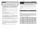
Make sure all accessories are rated for the recommended speed of the drill.
Brushes, grinding wheels and other accessories may fall apart if run at too high a
speed, sending dangerous debris flying at the operator.
Use gloves when changing hot bits and accessories to avoid burns.
SYMBOLS
IMPORTANT: Some of the following symbols may be used on your tool. Please
study them and learn their meaning. Proper interpretation of these symbols will
allow you to operate the tool better and safer.
SYMBOL NAME EXPLANATION
V Volts Voltage (Potential)
A Amperes Current
Hz Hertz Frequency (Cycles per Second)
W Watt Power
Kg Kilograms Weight
Alternating Current Type of Current
Direct Current Type of Current
Alternating or Direct Current Type of Current
Earthing Terminal Grounding Terminal
Class II Construction Denotes Double Insulation
min Minutes Time
s Seconds Time
Diameter Size of Drill Bits,
Grinding Wheels, etc.
No load speed No-load Rotational Speed
.../min Revolutions per Minute Revolutions, Surface Speed,
Strokes, etc. per Minute
1,2,3, … Ring Selector Settings Speed, Torque or Position Settings
1
2