


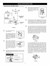
Gable Vent
,/too t%a,,
'nsulation
\
Conflne lI..
Space
ii
\Outlet Air
to the Attic
1 sq. in. per
4000 BTUH
Inlet Air
from the
Alternative Crawl Space
Air inlet I
1 sq. in. per / Open
4000 BTUH Foundation___
Vent
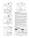
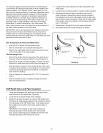
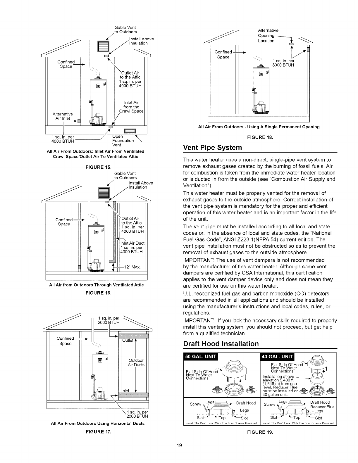
All Air From Outdoors: Inlet Air From Ventilated
Crawl Space/Outlet Air To Ventilated Attic
FIGURE 15.
Confined
Space 1 [
Gable Vent
to Outdoors
J Install Above
All Air from Outdoors Through Ventilated Attic
FIGURE 16.
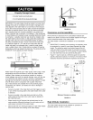
ConfinedI__L.
Space
1
sq. in. per _
2000 BTUH
Outlet,
Outdoor
Air Ducts
Inlet
\\1 sq.in.per
2000 BTUH
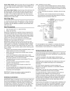
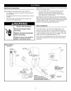
All Air From Outdoors Using HorizontalDucts
FIGURE 17.
19
Confined
Space
Alternative
Opening------..__...._]
Location ,_'
1 sq. in. per
3000 BTUH
All Air From Outdoors - Using A Single Permanent Opening
FIGURE 18.
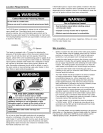
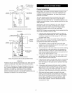
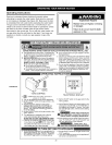
Vent Pipe System
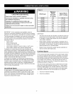
This water heater uses a non-direct, single-pipe vent system to
remove exhaust gases created by the burning of fossil fuels. Air
for combustion is taken from the immediate water heater location
or is ducted in from the outside (see "Combustion Air Supply and
Ventilation").
This water heater must be properly vented for the removal of
exhaust gases to the outside atmosphere. Correct installation of
the vent pipe system is mandatory for the proper and efficient
operation of this water heater and is an important factor in the life
of the unit.
The vent pipe must be installed according to all local and state
codes or, in the absence of local and state codes, the "National
Fuel Gas Code", ANSI Z223.1(NFPA 54)-current edition. The
vent pipe installation must not be obstructed so as to prevent the
removal of exhaust gases to the outside atmosphere.
IMPORTANT: The use of vent dampers is not recommended
by the manufacturer of this water heater. Although some vent
dampers are certified by CSA International, this certification
applies to the vent damper device only and does not mean they
are certified for use on this water heater.
U.L. recognized fuel gas and carbon monoxide (CO) detectors
are recommended in all applications and should be installed
using the manufacturer's instructions and local codes, rules, or
regulations.
IMPORTANT: If you lack the necessary skills required to properly
install this venting system, you should not proceed, but get help
from a qualified technician.
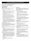
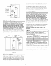
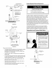
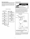
Draft Hood Installation
A
Fla_tSTeidco_ioWOnaftH°°d_ _
Screw , Legs!_ Draft Hood
% _, Legs
Slot Top Slot
Install The Draft Hood With The Four Screws Provided.
Flat Side Of Hood [ _
Next To Water _-
Connections. i!_ 41,
Installation above ........ _.,_,,
elevation 5,400 ft. _-::- :__
(1,646 m) from sea
level, Reducer Flue _ __must be installed on _
40 gallon unit.
S Legs _ _ Draft Hood
crew _ y ',/ Reducer Flue
"_"%_}i- _t_ 7_,,_-Legs
Slot _" _t To ) _ Sl0t
Install The Draft Hood With The Four Screws Provided.
FIGURE 19.