


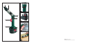

Initial Use
2. Place the battery pack
Y
in the fast charging
device
O
. The green charging control LED
P
ex-
tinquishes and the red charging control LED
{
,
now glowing, indicates the start of the charging
process. The red charging control LED
{
extin-
guishes as soon as the battery pack
Y
is fully
charged.
3. The green charging control LED
P
indicates that
charging is complete and the rechargeable battery
pack
Y
is ready for use.
4. Disconnect the mains plug of the fast charging
device
O
from the socket.
Remove the rechargeable battery pack
Y
.
j A rechargeable battery pack
Y
must never be
charged up a second time immediately after the
fast charging procedure. Otherwise there is a
danger that the rechargeable battery pack
Y
will
be overcharged, thus reducing the lifetime of the
rechargeable battery pack
Y
and the fast charging
device
O
.
j The charging device should be switched off for
at least 15 minutes between charging.
Please remove the mains plug.
L
Inserting and Removing the
Rechargeable Battery Pack
from the Device
Inserting the Rechargeable Battery Pack:
j Please move the direction of rotation switch
R
to the “lock” position and allow the rechargeable
battery pack
Y
to lock into place in the handle.
Removing the Rechargeable Battery Pack:
j Press the side release buttons
U
simultaneously
and remove the rechargeable battery pack
Y
.
L
Torque Pre-selection
The rotary force can be adjusted by means of the
torque pre-selector
W
. The torque levels go up to
approximately 9 Nm.
Once the rotary force that has been set (markings
1-15) is reached, the clutch disconnects the drive.
j Select a low level for small screws and soft ma-
terials.
j Select a high level for large screws, hard materials
and when loosening screws.
j If level 16 is selected, the clutch does not disconnect
the drive. The drive chain is locked in place. Select
this level if you require maximum rotary force.
L
Angular Position (Illustration A)
j Press and hold the angular position switch
E
(see illustration A).
j Move the device into the angular position
(no intermediate setting).
j Release the angular position switch
E
.
Check whether the screwdriver has locked in
place in the angular position.
L
Changing the Tool
Inserting
j Insert the bit into the tool holder
Q
.
Removing
j Remove the bit from the tool holder
Q
.
L
Switching on / off
Notice: If the rotation direction switch
R
is located in
the central / neutral position, the ON / OFF switch
I
is
blocked. Therefore select a rotation direction before
switching on, in that the rotation direction switch
R
is pushed through completely
j To switch the screwdriver on, press the ON / OFF
switch
I
and keep it pressed.
j To switch the screwdriver off, release the ON / OFF
switch
I
.
L
Setting the Speed
The ON / OFF switch
I
has a variable speed control.
Increasing the Speed
j Increase the pressure on the ON / OFF switch
I
.
8 GB/IE