


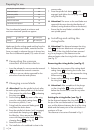
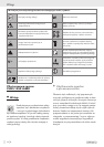
14 GB
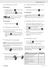
Acrylic glass panels, Plexiglas 2-4
Aluminium board 4-6
Aluminium profiles 4-6
Plasterboard 1-2
Mineral wool board 1-2
Cement-bound chipboard 1-2
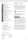
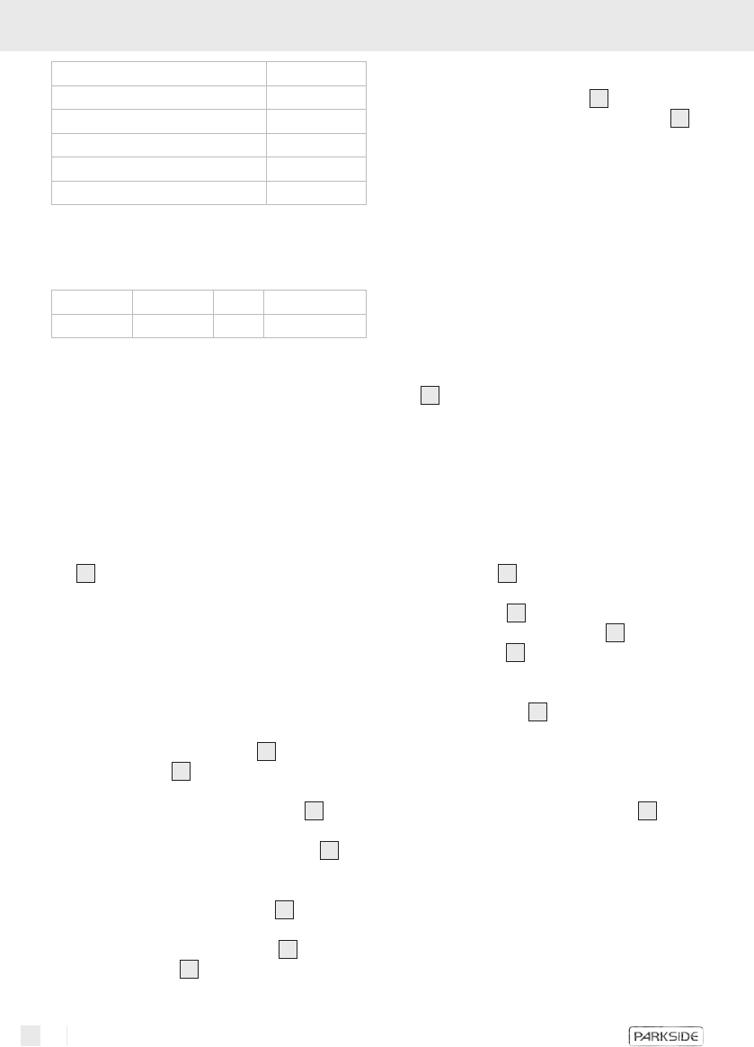
The circumferential speeds at minimum and
maximum rotational speeds are approx.:
Setting 1 1,800 rpm CS 20 metres/sec
Setting 6 5,000 rpm CS 55 metres/sec
Make sure that the cutting speed resulting from the
effects of different saw blades, materials and the
force you apply to advance the saw is always less
than the circumferential speed (CS) under no load.
Q
Connecting the vacuum
sawdust extraction device
j Insert the adapter for vacuum sawdust removal
24
into the sawdust removal connector.
j Connect a vacuum device approved for the
extraction of sawdust and splinters.
Q
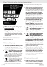
Changing a saw blade
m Attention! Press the spindle lock only after
the mains plug has been pulled out of the socket!
1. Then remove the guide fence
12
by releasing
the wing screw
10
.
2. Set the cutting depth (by means of the wing
screw for cutting depth setting clamp
5
) to
the minimum position, 0 mm.
3. Swing back the automatic blade guard
6
and place the device down.
4. Press the spindle lock button (until it engages)
and release the clamping screw
21
using
the Allen key. Now remove the clamping
screw with integral washer head
21
and the
clamping flange
20
(see Fig. D).
5. Detach the saw blade.
6. The installation of a sawblade is done in the
reverse order.
7. Press the spindle lock button
3
(until it
engages) and tighten the clamping screw
21
using the Allen key.
m Attention! The arrow on the saw blade must
agree with the arrow showing the direction of
rotation (running direction shown on the device).
j Ensure that the saw blade is suitable for the
saw spindle speed.
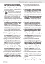
Q
Installing and setting the
riving knife
m Attention! The distance between the riving
knife
16
and the saw blade must not be greater
than 5 mm. If the riving knife has been removed
e.g. for a plunge cut, this distance must be
observed again when the riving knife is reinstalled
(see Fig. F).
Removing the riving knife: (see Fig. E)
1. Release the wing screws of the cutting depth
setting clamp
5
and swing the circular saw
up until it meets the stop; this exposes the riving
knife mounting
22
.
2. Screw out the mounting screws
23
and remove
the riving knife
16
.
m Attention! After completion of the plunge
cut the riving knife
16
must be reinstalled
before the circular saw is used for any other
sawing tasks.
Setting the riving knife: (see Fig. F)
Set the distance between the riving knife
16
and
the tips of the saw blade teeth to a maximum of 5
mm, and the distance between the tip of the riving
blade and the lowest point of the saw blade to a
maximum of 5 mm.
The distances to be set are illustrated in Fig. F.
Preparing for use