


For use with standard cuts, the mitre angle scale
P
has easily engaged fixed stop points for the most
common positions, 0°, 15°, 22.5°, 30° and 45°.
L
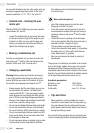
Inclined cuts – inclining the saw
motor unit
With the PKGS 1450 LASER you can make inclined
cuts between 90° and 45°.
j Loosen the setting knob
w
and using the scale
on the saw motor unit
[
set the angle for your
inclined cut. After you have set the angle and
before you make your cut make sure that you
tighten the setting knob
w
again.
L
Making a combination cut
To make a combination cut you have to incline the
saw motor unit
Q
and turn the saw table (see the
sections “Mitre cuts” and “Inclined cuts”).
L
Changing a saw blade
Warning! Always make sure that the mains plug
is out of the socket before doing any work on the
device. With the saw motor unit lowered, first lock
the machine by engaging the transport lock
o
.
j Always ensure that the saw blades you use are
as described in the section “Included items”,
comply with EN 847-1 and are properly sharp-
ened. Always use saw blades that have a diam-
eter of 250 mm and blade flanges specified for
this saw. Saw blades with hardened metal teeth
must have a positive cutting angle.
j Do not use saw blades that have deep hook teeth.
j Do not use saw blades that are recommended
for use at less than 4500 revolutions per minute.
j Do not use saw blades that are made from HSS
(high-speed steel). Do not use saw blades that
are damaged or deformed.
j Do not use spacer pieces or spindle rings in order
to allow other sizes of saw blade to be fitted.
Saw blades must be protected during transport
to prevent injury.
Wear protective gloves!
j Insert the locking spanner (e) into the outer
flange
u
and hold it in place.
j Place the wrench / socket spanner (f) into the
screw head and release the screw by turning it
clockwise. Remove the screw
y
and the outer
flange
u
.
j Unlock the device by pulling out the transport
lock
o
and carefully tilting the saw motor unit
Q
upwards. Caution - danger of injury!
The saw blade may have become loose.
j Unlock the automatic blade guard
R
by pushing
the safety lever
E
to the right. Push the auto-
matic blade guard
R
upwards.
j Now you can remove the blade by moving it
downwards.
The process for installing a saw blade is the reverse
(put on the flange, tighten the screw in the counter-
clockwise direction). Always check that you have
inserted the saw blade so that it rotates in the correct
direction. You will find the direction of rotation marked
on the saw blade and the saw motor unit
Q
.
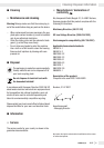
Saw blade parameters:
Diameter x bore: 250 x 30 mm
Blade width: 1.8 - 2.35 mm
Tooth width: max. 3.0 - 3.2 mm
L
Tips and tricks
j Never position a curved workpiece in such a
way that it curves away from the stop plate
q
.
Any gap between the stop plate and the work-
piece would cause the saw blade to be blocked
during the cutting process.
You can find further practical tips on electrical tools
in the accompanying booklet containing safety advice.
Operation
12 GB/IE