


Operation
3. Saw blade depth
Wear protective gloves!
j Check the depth of the saw blade by first lowering
the saw motor unit
Q
as far down as possible.
Then try turning the saw blade manually. It must
be able to turn freely. If the saw blade does not
turn freely, carry out the necessary adjustment
by turning the setting screw
p
.
4a. Mitre setting 0°
j If necessary you can adjust the 0° mitre stop. Bring
the saw table
T
into the basic position (0°setting).
With the saw motor unit
Q
lowered, compare
the alignment of the side face of the saw blade
with the workpiece support surface of the table
using a set square.
To make the adjustment, first loosen the lock
nut on the setting screw
]
(see Fig. A) and then
turn the screw with the supplied 5 mm Allen key
(d). Take off the Allen key – readjust until the
saw blade is at 90° to the saw table. Tighten the
locknut on the setting screw
]
. The saw blade
must be at right angles to the saw table and the
scale on the saw motor unit
Q
must read 0°.
4b. Mitre setting 45° (inclined cut setting)
j Set the saw table
T
into the basic position
(0° setting). Loosen the setting knob
w
and
incline the saw motor unit
Q
until the 45°
setting on the scale
[
on the saw motor unit
is reached. Retighten the setting knob
q
and
lower the saw motor unit
Q
.
j Use a combination set square to check the angle
of the side face of the saw blade with respect to
the workpiece support area of the saw table. To
make the adjustment first loosen the lock nut on
the setting screw
S
(see Fig. B) and then turn
the screw with the supplied 5 mm Allen key (d).
Take off the Allen key – readjust until the saw
blade is at 45° to the saw table. Tighten the
locknut on the setting screw
S
.
5. Adjusting the pointer on the scale
[
If the pointer when it is in the basic setting is not in
line with the 0° marking on the scale then adjust the
pointer as follows:
j First make sure that the basic settings 0° and
45° have been carried out correctly as descri-
bed in sections 4a and 4b.
j Loosen the setting knob
w
and incline the saw
motor unit
Q
into the 45° setting.
j Loosen the pointer screw with a cross-head
screwdriver and adjust the pointer until it is in
line with the 45° marking and tighten the screw
again. After you have returned the saw motor
unit
Q
into the 0° position, the pointer should
again be exactly in line with the 0° marking on
the scale. If necessary repeat the adjustment
process until the pointer is correctly set.
L
Operation
Take note of the mains voltage! The voltage must agree
with that shown on the machine rating plate (equip-
ment shown as 230 V can also be connected to 220 V).
L
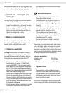
Connecting a dust extraction device
The dust created when sawing can be inflammable,
explosive and hazardous to health. Some dusts are
carcinogenic. Use a suitable dust extraction device
designed for the purpose and wear a dust protection
mask.
Wear a dust mask!
External vacuum extraction:
j Connect a vacuum extraction device of a type
specifically suitable for dust extraction to the
sawdust removal connector
r
. Ensure that you
connect and use it properly.
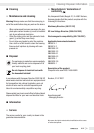
Sawdust collection bag (a):
j Attach the sawdust collection bag (a) to the sa-
wdust removal connector
r
by pressing the
lugs of the wire ring together. Engage the wire
ring in the groove provided in the sawdust re-
moval connector.
j To remove the sawdust collection bag (a) from
the sawdust removal connector
r
you also
press the lugs of the wire ring together.
10 GB/IE