


14 GB
Operation
Q
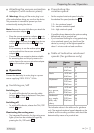
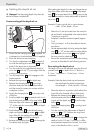
Setting the depth of cut
m Danger! Set the cutting depth only after the
device has been switched off!
Coarse setting of the depth of cut
1.0
3/64
1/32
16
14
13
1. Ensure that the clamping lever
15
is applied. If it
is released turn it anticlockwise until it is applied.
2. Place the device on the workpiece.
3. Turn the fine adjustment knob
14
for depth of
cut until the markings for zero-reset
16
on the
back of the device are in alignment.
4. Turn the scale for fine adjustment of depth of
cut in mm
13
until the “0” point aligns with the
marking on the housing.
5. Turn the step buffer
7
until it engages in the
lowest position.
6. Release the stop screw
9
for depth stop.
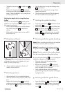
7. Release the clamping lever
15
by turning it
clockwise and press the device downwards
until the router bit comes into contact with the
workpiece surface.
8. Apply the clamping lever
15
by turning it anti-
clockwise.
9. Push the depth stop
10
downwards until it is sit-
ting at the lowest position of the step buffer
7
.
Press the slider with index mark
11
to position
“0” of the scale for coarse adjustment of depth
of cut in mm
12
.
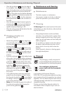
10. Set the depth stop
10
to the desired routing
depth and tighten the stop screw
9
for depth
stop. After this, the setting of the slider with
index mark
11
should not be changed.
11. Release the clamping lever
15
and then guide
the device back up again.
After setting the depth of cut do not change the set-
ting of the slider with index mark
11
on the depth
stop
10
. The current depth of cut setting can now be
read on the scale for coarse adjustment of depth of
cut in mm
12
.
Example: Create a guide slot in a pine drawer:
width: 16 mm, depth: 10 mm
j Select the 16 mm slot cutter from the router bit
set and insert it as described in the section about
“Inserting a router bit”.
j Preselect a medium rotational speed (approx.
3 - 4).
j Carry out steps 1 to 9 as described in the sec-
tion above.
j Set the required depth of cut by setting the depth
stop
10
to “10” on the scale for coarse adjust-
ment of depth of cut in mm
12
. Now tighten
the stop screw for depth stop
9
.
j Secure the workpiece and carry out the routing
process as described in the following sections.
Fine setting the depth of cut
The depth of cut can be adjusted using the fine ad-
justment knob
14
for depth of cut. (1 division =
0.1 mm / 1 revolution = 1.5 mm) max. + - 8 mm
movement.
Example: Take the device back up and measure
the machined slot depth (required ma-
chined depth = 10 mm / actual = 9.8 mm)
j Place the device in a position which allows the
router bit to be lowered without obstruction.
j Release the clamping lever
15
by turning it
clockwise and press the device carefully down-
wards until the depth stop
10
sits on the step
buffer
7
.
j Apply the clamping lever
15
by turning it anti-
clockwise.
j Turn the scale for fine adjustment of depth of
cut in mm
13
to “0”. Release the stop screw
9
for depth stop
10
.
j Use the fine adjustment knob
14
to change the
depth of cut by 0.2 mm / 2 divisions (= differ-
ence between required and actual), turn clock-
wise, in the direction of the + arrow.