corrosion.
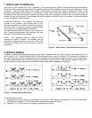
・ The solar module frame must be attached to a support structure using ¼” or M6 stainless steel hardware in a
minimum of four (4) places symmetrical on the solar module. The stainless steel hardware used for securing the
module frame should secured with an applied torque of 6 foot-pounds (8 Newton-meters).
・ Module support structures that are to be used to support Kyocera Solar modules should be wind rated and
approved for use by the appropriate local and civil codes prior to installation.
GROUNDING
・ All module frames and mounting racks must be properly grounded in accordance with local and national electrical
codes.
INSPECTION
・ Follow the requirements of applicable local and national electrical codes.
BATTERY
・ When solar modules are used to charge batteries, the battery must be installed in a manner which will protect the
performance of the system and the safety of its users. Follow the battery manufacturer’s guidelines concerning
installation, operation and maintenance recommendations. In general, the battery (or battery bank) should be
away from the main flow of people and animal traffic. Select a battery site that is protected from sunlight, rain,
snow, debris, and is well ventilated. Most batteries generate hydrogen gas when charging, which can be explosive.
Do not light matches or create sparks near the battery bank. When a battery is installed outdoors, it should be
placed in an insulated and ventilated battery case specifically designed for the purpose.
5. SITE SELECTION
In most applications, KC modules should be installed in a location where they will receive maximum sunlight throughout
the year. In the Northern Hemisphere, the modules should typically face south, and in the Southern Hemisphere, the
modules should typically face north. Modules facing 30 degrees away from true South (or North) will lose approximately
10 to 15 per cent of their power output. If the module faces 60 degrees away from true South (or North), the power loss
will be 20 to 30 per cent. When choosing a site, avoid trees, buildings or obstructions which could cast shadows on the
solar modules especially during the winter months when the arc of the sun is lowest over the horizon.
6. MODULE TILT ANGLE
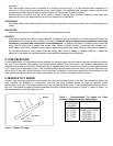
Kyocera solar modules produce the most power when they are pointed directly at the sun. For installations where the
solar modules are attached to a permanent structure, the solar modules should be tilted for optimum winter
performance. As a rule, if the system power production is adequate in the winter, it will be satisfactory during the rest of
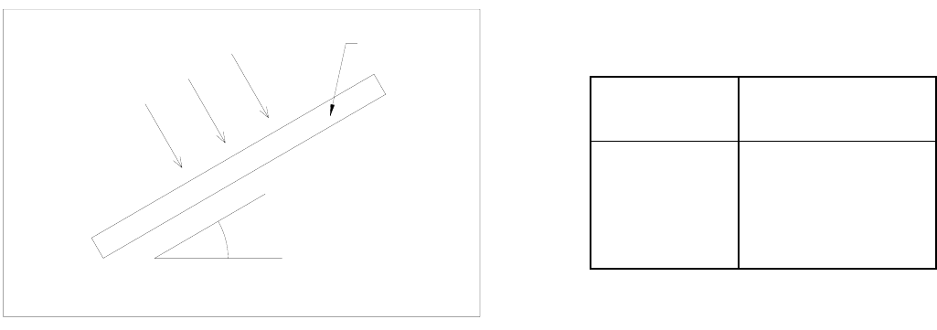
the year. The module tilt angle is measured between the solar modules and the ground (Figure 1). Refer to Table 1 for
the recommended module tilt angle your site.
MODULE
SUNLIGHT
TILT ANGLE
HORIZONTAL
Figure 1. Module Tilt Angle
Table 1. Recommended Tilt Angles for Fixed
Systems—Based on Winter Performance
SITE
LATITUDE IN
DEGREES
FIXED TILT ANGLE
0°TO 15
15°TO 25°
25°TO 30°
30°TO 35°
35°TO 40°
40°+
15°
SAME AS LATITUDE
LATITUDE + 5°
LATITUDE + 10°
LATITUDE + 15°
LATITUDE + 20°


