When a bypass diode is wired in parallel with the series string, the forced current will flow through the diode and bypass
the shaded module, thereby minimizing module heating and array current losses.
For 12-volt systems and higher: Each module junction box has a diagram illustrating the proper orientation of the
bypass diode installed between two of the terminal screws (Figure 11, Figure 12). When the solar modules are
connected as individual series strings first, and then these strings are connected in parallel, bypass diodes should be
used in each junction box. This is the simplest wiring arrangement for most installations.
Diodes that are used as bypass diodes must:
・ Have a Rated Average Forward Current [I
F(AV)
] Above maximum system current at highest module operating
temperature.
・ Have a Rated Repetitive Peak Reverse Voltage [V
RRM
] Above maximum system voltage at lowest module
operating temperature.
12. MAINTENANCE
Kyocera modules are designed for long life and require very little maintenance. Under most weather conditions, normal
rainfall is sufficient to keep the module glass surface clean. If dirt build-up becomes excessive, clean the glass surface
only with a soft cloth using mild detergent and water. USE CAUTION WHEN CLEANING THE BACK SURFACE OF
THE MODULE TO AVOID PENETRATING THE PVF SHEET. Modules that are mounted flat (0°tilt angle) should be
cleaned more often, as they will not "self clean" as effectively as modules mounted at a 15°tilt or greater. Once a
year, check the tightness of terminal screws and the general condition of the wiring. Also,
check to be sure that
mounting hardware is tight. Loose connections will result in a damaged module or array.
13. SPECIFICATIONS
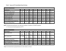
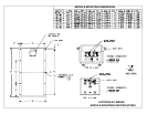
The electrical and physical specifications can be found at the end of this document (Table 2).
NOTES
・ The electrical characteristics are within ±10 percent of indicated values of Isc, Voc, and Pmax under standard test
conditions (irradiance of 1KW/m
2
, AM 1.5 spectrum, and cell temperature of 25℃).
・ Under certain conditions, a photovoltaic module is likely to produce more current and / or voltage than reported at
standard test conditions. Accordingly, the values of Isc and Voc marked on this module should be multiplied by a
factor of 1.25 when determining component voltage ratings, conductor ampacities, fuse sizes, and sizes of
regulators which are connected to the PV output. Refer to Section 690-8 of the National Electrical Code for an
additional multiplying factor of 125 (80 per cent derating) which may also be applicable.
MANUFACTURED IN JAPAN BY KYOCERA CORPORATION
KSI GROUP
Kyocera Solar Inc. (Headquarters)
7812 East Acoma Drive, Scottsdale, AZ 85260, USA
Tel: (480) 948-8003 or (800) 223-9580
Fax: (480) 483-6431
www.kyocerasolar.com
Kyocera Solar Pty, Ltd.
36 Windorah St., Unit 6 Stafford 4053 Queensland, Australia
Tel: (61) 7-3856-5388
Fax: (61) 7-3856-5443
Kyocera Solar Argentina S.A.
Mejico 2145, 16400 Martinez Prov. de Buenos Aires Argentina
Tel: (54) 114-836-1040
Fax: (54) 114-836-0808
Kyocera Solar Do Brazil
Rua Mauricio da Costa Faria, 85
22780-280 – Recreio – Rio de Janeiro
Tel: (55) 2-1554-5554
Fax: (55) 2-1553-4894
KFG GROUP
Kyocera Fineceramics GmBH
Fritz Müller Strasse 107, D-73730 Esslingen, Germany
Phone: (49) 711-9393-417
Fax: (49) 711-9393-450
www.kyocera.de/products/solar.htm
KAP GROUP
Kyocera Asia Pacific Singapore
Fritz Müller Strasse 107, D-73730 Esslingen, Germany
298 Tiong Bahru Road, #13-03/05 Tiong Bahru Plaza Singapore
168730
Tel: (65) 271-0500
Fax: (65) 271-0600


