


THUMB
SCREW
GUN
A-5
INSTALLATION
A-5
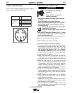
PRESSURE ARM ADJUSTMENT
ELECTRIC SHOCK can kill.
• Turn the input power OFF at the weld-
ing power source before installation or
changing drive rolls and/or guides.
• Do not touch electrically live parts.
• When inching with the gun trigger, electrode
and drive mechanism are "hot" to work and
ground and could remain energized several sec-
onds after the gun trigger is released.
• Do not operate with covers, panels or guards
removed or open.
• Only qualified personnel should perform mainte-
nance work.
------------------------------------------------------------------------
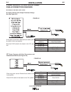
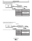
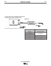
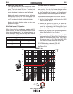
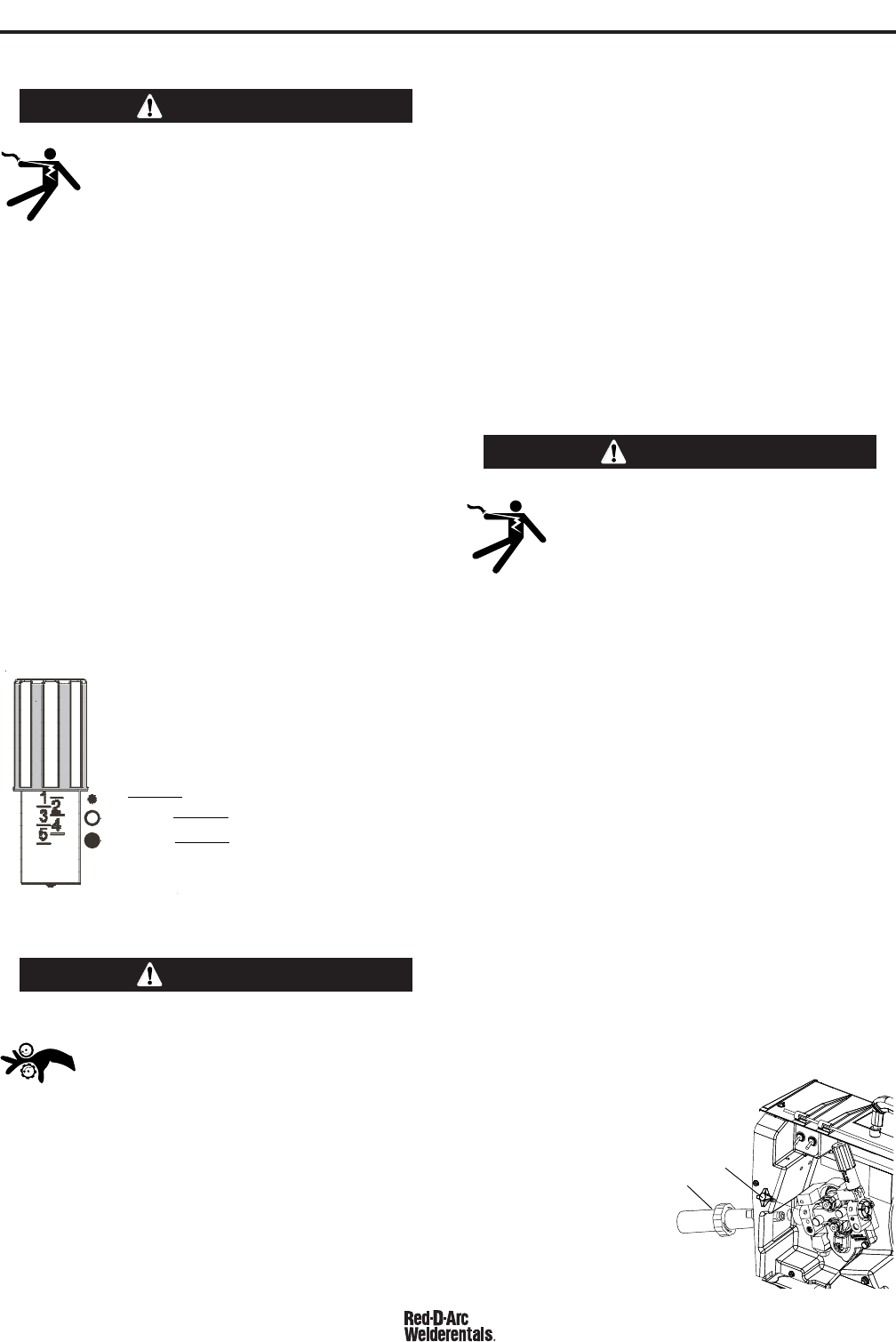
The pressure arm controls the amount of force the
drive rolls exert on the wire. Proper adjustment of the
pressure arm gives the best welding performance.
Set the pressure arm as follows:
(See Figure A.3)
Aluminum wires between 1 and 3
Cored wires between 3 and 4
Steel, Stainless wires between 4 and 6
LOADING SPOOLS OF WIRE
• Keep hands, hair, clothing and tools
away from rotating equipment.
• Do not wear gloves when threading wire
or changing wire spool.
• Only qualified personnel should install,
use or service this equipment.
------------------------------------------------------------------------
Loading 10 to 15 lb. (4.5 – 6.8kg) Spools.
A K468 spindle adapter is required for loading 2"
(51mm) wide spools on 2" (51mm) spindles. Use a
K468 spindle adapter for loading 2-1/2" (64mm) wide
spools.
1. Squeeze the release bar on the retaining collar and
remove it from the spindle.
2. Place the spindle adapter on the spindle, aligning
the spindle brake pin with the hole in the adapter.
3. Place the spool on the spindle and align the
adapter brake tab with one of the holes in the back
side of the spool. An indicator mark on the end of
the spindle shows the orientation of the brake tab.
Be certain the wire feeds off of the spool in the
proper direction.
4. Re-install the retaining collar. Make sure that the
release bar snaps out and that the retaining collar
fully engages the groove on the spindle.
GUN CONNECTION
ELECTRIC SHOCK can kill.
• Turn the input power OFF at the weld-
ing power source before installation or
changing drive rolls and/or guides.
• Do not touch electrically live parts.
• When inching with the gun trigger, electrode
and drive mechanism are "hot" to work and
ground and could remain energized several sec-
onds after the gun trigger is released.
• Do not operate with covers, panels or guards
removed or open.
• Only qualified personnel should perform mainte-
nance work.
------------------------------------------------------------------------
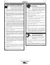
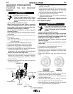
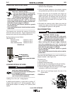
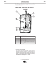
The LN25 PRO EXTREME comes with a K1500-2 gun
adapter installed. (See Figure A.4)
To install a gun,
1. Turn power OFF.
2. Remove the thumb screw.
3. Push the gun the completely into the gun bushing.
4. Secure the gun in place with the thumb screw.
5. Connect the trigger cable from the gun to the trigger
connector on the front of the feeder.
Note: Not all gun bushings require the use of the
thumb screw.
WARNING
WARNING
6
Al
Fe, CrNi
Fe, CrNi
ALUMINUM WIRES
CORED WIRES
STEEL, STAINLESS WIRES
FIGURE A.3
WARNING
FIGURE A.4
LN-25 PRO EXTREME