


$%')$#
%9<?D<978D indicates when the supply lines to the
welder are electrically "hot". This means that the
welder input power and control transformers are ener-
gized when the pilot light is on.
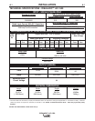
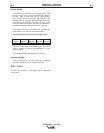
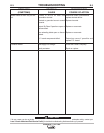
>@ED9B3E9D%<1> The AC-1500 is not intended for
the connection of flexible supply cables. Instead, the
following table may be used for planning of supply
cables routed in conduit (See Technical Specifications
in the Installation Section).
(D1BD9>75F935 The pushbuttons located on the
front panel are not connected to any kind of starting or
stopping device. They are not necessary to operating
the welder. If pushbutton operation is desired, an input
contactor must be professionally installed and wired to
the pushbutton assembly. The AC-1500 does not
have an input contactor. Therefore, include an exter-
nal starter or disconnect switch when planning the
input circuit. Once the input circuit is energized, the
pilot light on the front panel should glow. High voltage
is present inside the machine. Do not open the
machine enclosure.
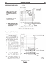
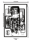
>@ED%1>5< is made accessible by removal of the
right side panel assembly (as viewed from front).
Supply lines and grounding lead should be brought
into the welder through the hole provided in the case
rear panel. Connections to the input panel should be
made as instructed on the wiring diagram attached to
the welder. The grounding lead connection is to be
made to the grounding stud provided on the welder
base directly below the input panel.
!?31D9?>?69>CD1<<1D9?> should be such that the
welder cooling air exhaust area (the case rear panel)
is free of any obstructions that could impede air flow.
A dry location should be chosen. The welder should
not be placed on a surface that is inclined enough that
it creates a risk of the machine falling over
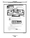
?>DB?<9B3E9D connections for wire feeder equip-
ment are to be made per instructions on the wire feed-
er diagram to the terminal strip provided under the
hinged cover on the case front panel of the welding
power supply. A strain relief strap to the right of the
terminal strip is provided for attaching either the feed-
er control and remote current control cables or both
simultaneously. A grounding screw located just to the
right of the terminal strip is provided for connecting the
wire feeder grounding lead. All connections must be
made with the welding power supply turned off.
!'P
1>4,5<49>7 with stick electrode or semiautomatic
arc welding is not recommended since OCV exceeds
the 80 volts RMS limit allowed by standards for such
use. (Unit is within 100 volt allowable limit for auto-
matic or mechanically guided welding.)
(3?DD?>>53D9?> information for tandem arc applica-
tion and paralleling of Scott connected units for tan-
dem arc application is available. (See list of wiring
diagrams.)
IC?<1D54EH9<91BI%?G5B of 1000 volt.-amp., 115
volts AC is available at terminals #31 and #32 on the
terminal strip under the hinged cover on the case front
panel of the welder. The circuit is fused with an 8
amp slow blow fuse located in the nameplated section
of the welder front panel.