


)8
*(%+")%%*$
Observe all Safety Guidelines detailed throughout this manual
%+*&+*&(%"#)
&(%"#)
).#&*%#)
&%))"
+)
(%##$
%+()%*%$
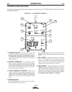
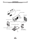
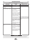
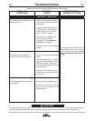
Major physical or electrical damage
is observed when cover wrap-around
is removed.
The machine is dead - no output.
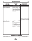
No output but the fan operates nor-
mally.
1. The input power switch must be
in the ON position.
2. Make sure the input voltage is
correct for the machine.
3. If the machine is set for single-
phase operation, inspect to
assure that the WHITE and
BLACK leads are connected
properly and the RED lead is not
connected and is insulated.
4. Check that the input voltage set-
up switch and jumper “A” (the
reconnect auxiliary jumper) are in
the proper position for the input
voltage being applied. Refer to
=?DC ,>;C064 (42>==42C
&A>243DA4in the Installation
Chapter.
5. Check continuity of the 0.6-amp
slow blow fuse located on the
reconnect panel.
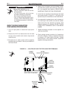
1. If the machine has not been used
for a long time and is connected
for 380 VAC or higher, the
capacitors may need “condition-
ing”. See Input Filter Capacitor
Conditioning.
2. The machine may be overheated.
Check the thermal indicator light.
Wait for the machine to cool and
the thermostats to reset.
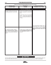
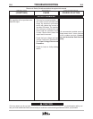
If all recommended possible areas of
misadjustment have been checked
and the problem persists, >=C02C
H>DA;>20;DC7>A8I4384;3)4AE824
028;8CH
If for any reason you do not understand the test procedures or are unable to perform the tests/repairs safely, con-
tact your local authorized field service facility for technical troubleshooting assistance before you proceed.
+*%$