


A-4
INSTALLATION
BULLDOG™ 140
A-4
ELECTRICAL OUTPUT
CONNECTIONS
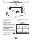
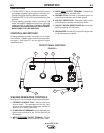
See Figure A.1 for the location of the current control
dial, weld output terminals, ground stud, circuit
breakers, 240 and 120 volt receptacles.
WELDING CABLE CONNECTIONS
Cable Size and Length
Be sure to use welding cables that are large enough.
The correct size and length becomes especially
important when you are welding at a distance from
the welder.
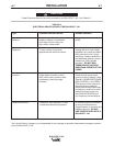
Table A.1 lists recommended cable sizes and lengths
for rated current and duty cycle. Length refers to the
distance from the welder to the work and back to the
welder. Cable diameters are increased for long cable
lengths to reduce voltage drops.
BULLDOG™ 140 OUTPUT CONNECTIONS
1. CURRENT CONTROL DIAL
2. WELD OUTPUT TERMINALS (2)
3. GROUND STUD
4. CIRCUIT BREAKER 20 Amp
5. RECEPTACLE - 240 VOLT, 50 AMP
6. DUPLEX RECEPTACLE (2)- 120 VOLT, 20
AMP
7. HOUR METER
FIGURE A.1
1
2
6
7
5
3
4
TOTAL COMBINED LENGTH OF
ELECTRODE AND WORK CABLES
Cable
Length
0-50 ft (0-15m)
50-100 ft (15-30 m)
100-150 ft (30-46 m)
150-200 ft (46-61 m)
200-250 ft (61-76m)
125 Amps
30% Duty Cycle
6 AWG
5 AWG
3 AWG
2 AWG
1 AWG
TABLE A.1
RECOMMENDED WELDING CABLE
SIZE AND LENGTH