


A-5
INSTALLATION
BULLDOG™ 140
A-5
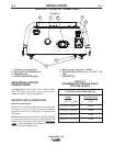
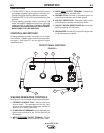
Cable Installation
Install the welding cables to your BULLDOG™ 140 as
follows. See Figure A.1 for the location of parts.
1. The gasoline engine must be OFF to install weld-
ing cables.
2. Remove the 1/2 - 13 flanged nuts from the output
terminals.
3. Connect the electrode holder and work cables to
the weld output terminals. You can connect either
cable to either terminal, since the BULLDOG™
140 provides AC weld current.
4. Tighten the flanged nuts securely.
5. Be certain that the metal piece you are welding
(the “work”) is securely connected to the work
clamp and cable.
6. Check and tighten the connections periodically.
• Loose connections will cause the output termi-
nals to overheat. The terminals may eventually
melt.
• Do not cross the welding cables at the output
terminal connection. Keep the cables isolated
and separate from one another.
-----------------------------------------------------------
Lincoln Electric offers a welding accessory kit with
the properly specified welding cables. See the
ACCESSORIES section of this manual for more infor-
mation.
ELECTRICAL CONNECTIONS
MACHINE GROUNDING
Because this portable engine driven welder creates its
own power, it is not necessary to connect its frame to
an earth ground, unless the machine is connected to
premises wiring (home, shop, etc.)
To prevent dangerous electric shock, other equipment
to which this engine driven welder supplies power
must:
1. Be grounded to the frame of the welder using a
grounded type plug.
2. Be double insulated.
Do not ground the machine to a pipe that carries
explosive or combustible material.
-----------------------------------------------------------------------
When the BULLDOG™ 140 is mounted on a truck or
a trailer, the machine generator ground stud MUST
be securely connected to the metal frame of the vehi-
cle. See Figure A.1. The ground stud is marked with
the symbol .
PLUGS AND HAND-HELD EQUIPMENT
For further protection against electric shock, any
electrical equipment connected to the generator
receptacles must use a three-blade, grounded type
plug or an Underwriter’s Laboratories (UL) approved
double insulation system with a two-blade plug.
Ground fault protection is recommended for hand
held equipment.
Never operate this machine with damaged or
defective cords. All electrical equipment must be
in safe condition.
-----------------------------------------------------------
AUXILIARY POWER RECEPTACLES
The control panel of the BULLDOG™ 140 features
two auxiliary power receptacles:
• A 20 amp, 120 volt duplex (double outlet) recepta-
cle
• A 20 amp 240 volt simplex (single outlet) recepta-
cle.
See Figure A.1.
Through these receptacles the machine can supply
up to 4,000 rated continuous watts and 5,500 surge
watts of single-phase AC power.
CAUTION
WARNING
WARNING