


$%')$#
,!#%'$((
For any electrodes the procedures should be kept
within the rating of the machine. For electrode infor-
mation see the appropriate Lincoln publication.
() $#()#)*''#),!#
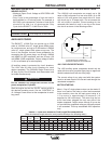
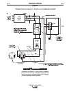
Connect welding cables to the "TO WORK” and
"ELECTRODE” studs. Start the engine. Set the
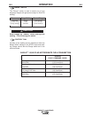
"Polarity” switch to the desired polarity. The “RANGE”
switch markings indicate the maximum current for that
range as well as the typical electrode size for that
range. The “OUTPUT” Control provides fine adjust-
ment of the welding current within the select range.
For maximum output within a selected range set the
“OUTPUT” Control at 10. For minimum output within a
selected range set the “OUTPUT” Control at 5. (“OUT-
PUT” Control settings below 5 may reduce arc stabili-
ty) For best overall welding performance set the
“RANGE” Switch to the lowest setting and the OUT-
PUT” Control near the maximum to achieve the
desired welding current.
'#())# ).%! *''#)'#
!)'$(/
The EAGLE™ 10,000 Plus can be used with a broad
range of DC stick electrodes. See “Welding Tips 1”
included with the EAGLE™ 10,000 Plus for electrodes
within the rating of this unit and recommended weld-
ing currents of each.
(')()'))$#()#)*''#)
,!#
The EAGLE™ 10,000 Plus can be used for Scratch-Start of DC
TIG welding applications. To initiate a weld, the course and fine
output control knobs must be set for the desired current. The
tungsten electrode is then scratch on the work which establish-
es the arc.
To stop the arc, simply lift the TIG torch away from the work
piece. The tungsten may then be scratched on the work piece
to restrike the arc.
If a high frequency start is desired, the K930-2 TIG Module can
be used with the EAGLE™ 10,000 Plus. The settings are refer-
enced.
The EAGLE™ 10,000 Plus and any high frequency generating
equipment must be properly grounded. See the K930-2 TIG
Module operating manuals for complete instructions on installa-
tion, operation and maintenance.
When using the TIG Module, the OUTPUT control on
the
EAGLE™ 10,000 Plus is used to set the maximum range of
the CURRENT CONTROL on the TIG Module or an Amptrol if
connected to the TIG Module.
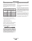
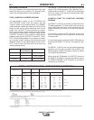
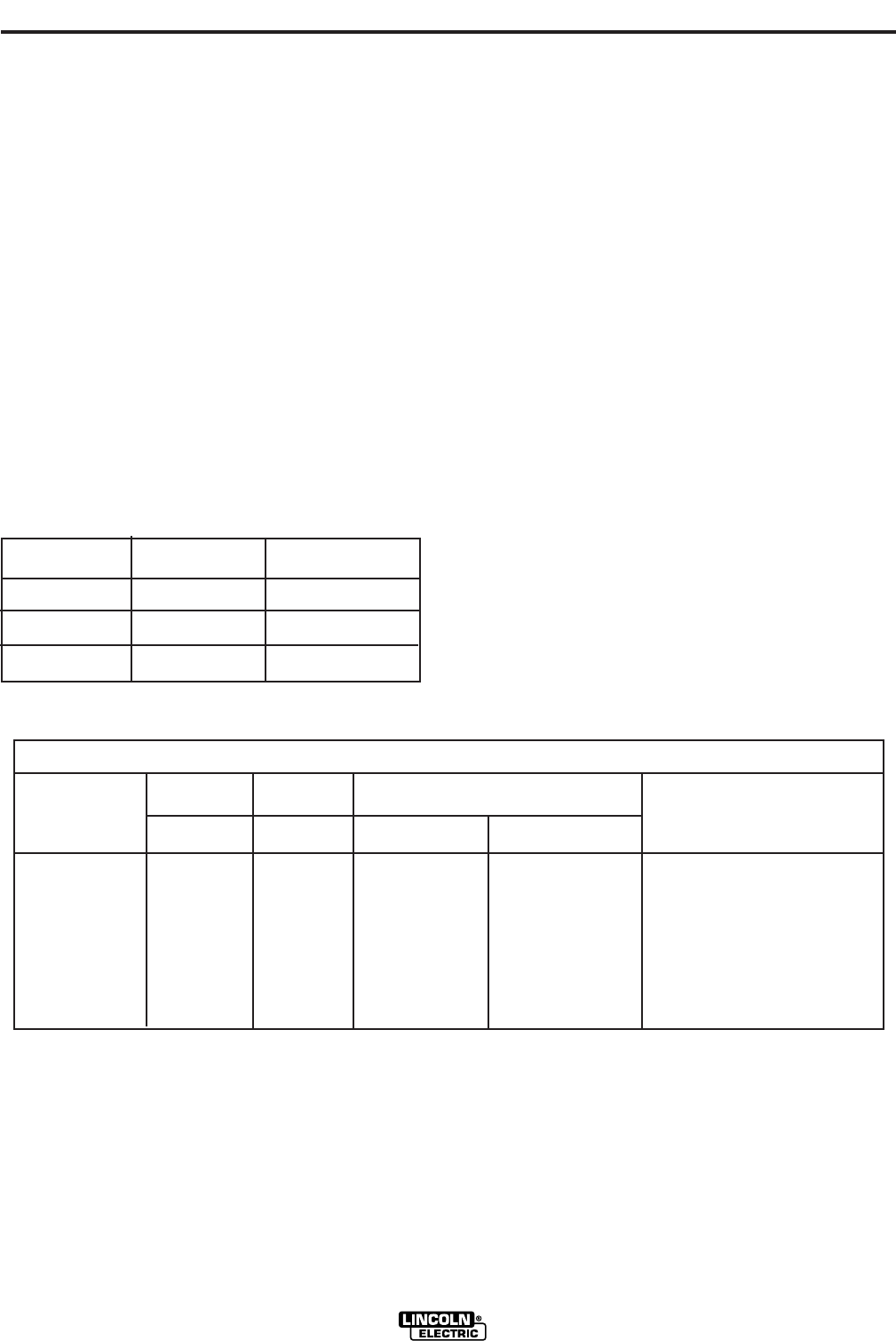
!Q%!*(
90 MAX.
145 MAX.
225 MAX.
3/32
1/8
5/32
40 TO 90 AMPS
70 TO 145 AMPS
120 TO 225 AMPS
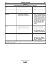
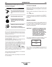
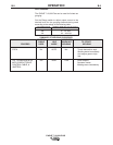
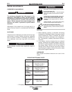
).%!*''#)'#(
$')*#()#!)'$(
Tungsten Electrode DDENE (-) DAZE (+) Approximate Argon Gas Flow TIG TORCH
Diameter in. (mm) Flow Rate C.F.H. ( l /min.) Nozzle Size (4), (5)
1%, 2% Thoriated 1%, 2% Thoriated Aluminum Stainless Steel
Tungsten Tungsten
.010 (.25) 2-15 (3) 3-8 (2-4) 3-8 (2-4) #4, #5, #6
0.020 (.50) 5-20 (3) 5-10 (3-5) 5-10 (3-5)
0.040 (1.0) 15-80 (3) 5-10 (3-5) 5-10 (3-5)
1/16 (1.6) 70-150 10-20 5-10 (3-5) 9-13 (4-6) #5, #6
3/32 (2.4) 150-250 15-30 13-17 (6-8) 11-15 (5-7) #6, #7, #8
1/8 (3.2) 250-400 25-40 15-23 (7-11) 11-15 (5-7)
5/32 (4.0) 400-500 40-55 21-25 (10-12) 13-17 (6-8) #8, #10
3/16 (4.8) 500-750 55-80 23-27 (11-13) 18-22 (8-10)
1/4 (6.4) 750-1000 80-125 28-32 (13-15) 23-27 (11-13)
(1) When used with argon gas. The current ranges shown must be reduced when using argon/helium or pure helium shielding gases.
(2) Tungsten electrodes are classified as follows by the American Welding Society (AWS):
Pure EWP
1% Thoriated EWTh-1
2% Thoriated EWTh-2
Though not yet recognized by the AWS, Ceriated Tungsten is now widely accepted as a substitute for 2% Thoriated Tungsten in AC and DC applications.
(3) DAZE is not commonly used in these sizes.
(4) TIG torch nozzle "sizes" are in multiples of 1/16ths of an inch:
# 4 = 1/4 in. (6 mm)
# 5 = 5/16 in. (8 mm)
# 6 = 3/8 in. (10 mm)
# 7 = 7/16 in. (11 mm)
# 8 = 1/2 in. (12.5 mm)
#10 = 5/8 in. (16 mm)
(5) TIG torch nozzles are typically made from alumina ceramic. Special applications may require lava nozzles, which are less prone to breakage, but cannot withstand high temperatures
and high duty cycles.