


B-2
OPERATION
B-2
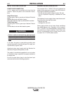
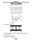
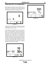
REAR CONTROL PANEL (FIGURE B.1)
• I1: Off/On switch turns on the electric power to
the welder. It has two positions, "O" off, and
"I" on.
------------------------------------------------------------
* With "l1" in the "I" (ON) position, the welding
machine is operational and there is voltage between
the positive (+) and negative (-) Terminals in stick
welding. In TIG, the welding process needs a trigger
closure command at the remote control connec-
tion.(Usually via an Arc Start Switch or Foot Amptrol)
* The welder is connected to the supply even if the
“l1” (Power Switch) is in the "O" (Off) position, and
therefore there are electrically live parts inside the
power source. Carefully follow the instructions given
in this manual.
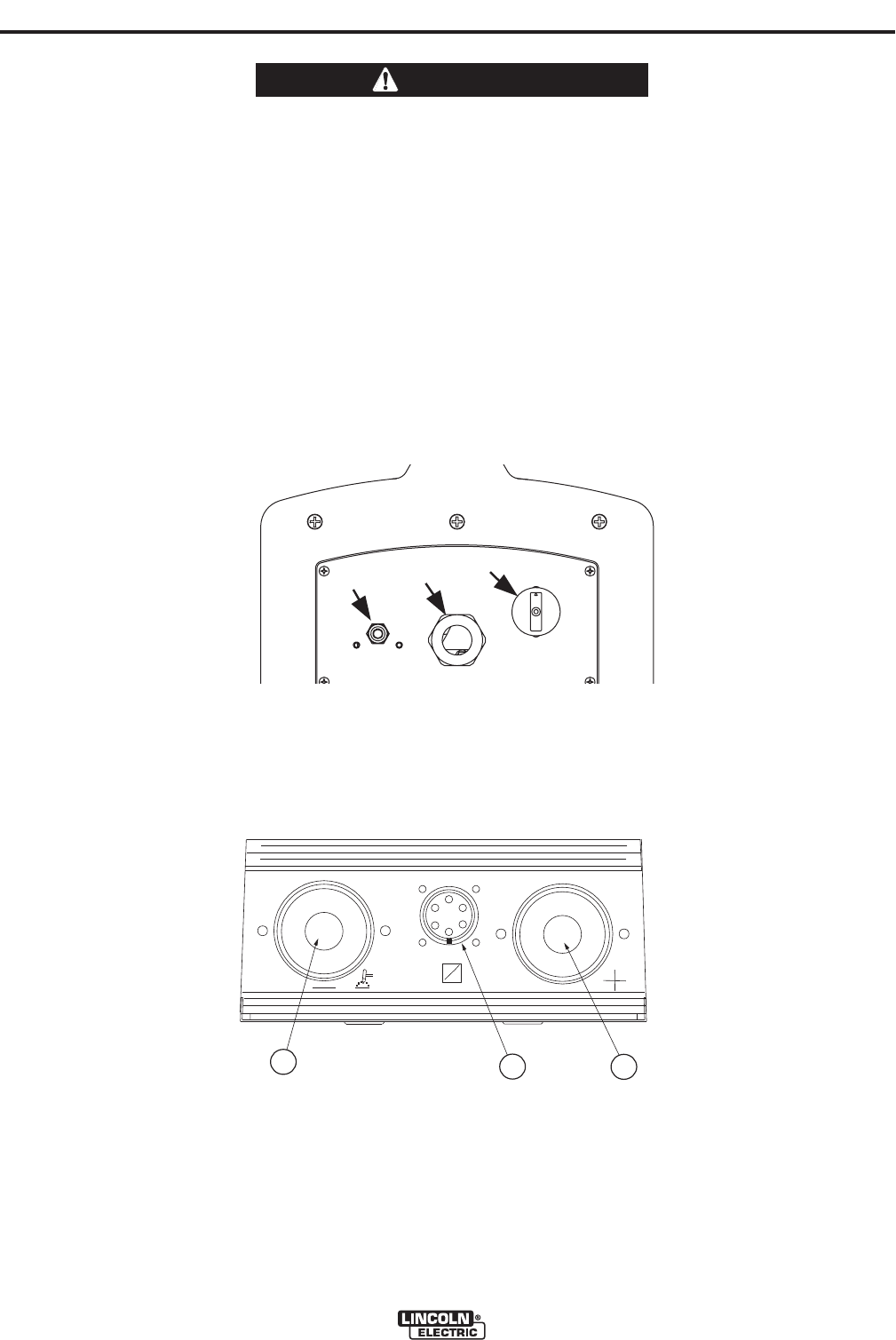
FIGURE B.1
* 1 : Supply cable
* 2 : Gas attachment
l1 : Power Switch
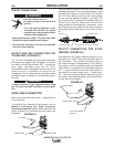
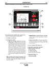
LOWER CONTROL PANEL (FIGURE B.2)
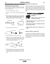
1. Electrode Connection (Negative) - For quick dis-
connect system using Twist-Mate cable plugs with
gas pass through for TIG Torches.
2. Remote Control Connector - For the connection
of a Lincoln Foot Amptrol, Hand Amptrol or Arc
Start Switch. See the ACCESSORIES section for
available options.
3. Electrode Connection (Positive) - For quick dis-
connect system using Twist-Mate cable plugs.
INVERTEC® V311-T AC/DC TIG
1
2
I1
WARNING
1
2
3
FIGURE B.2