


B-4
OPERATION
B-4
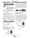
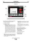
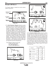
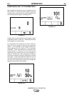
DYNAMIC LCD DISPLAY
The Dynamic display is divided into several sections
(Refer to Figure B.4):
Figure B.4
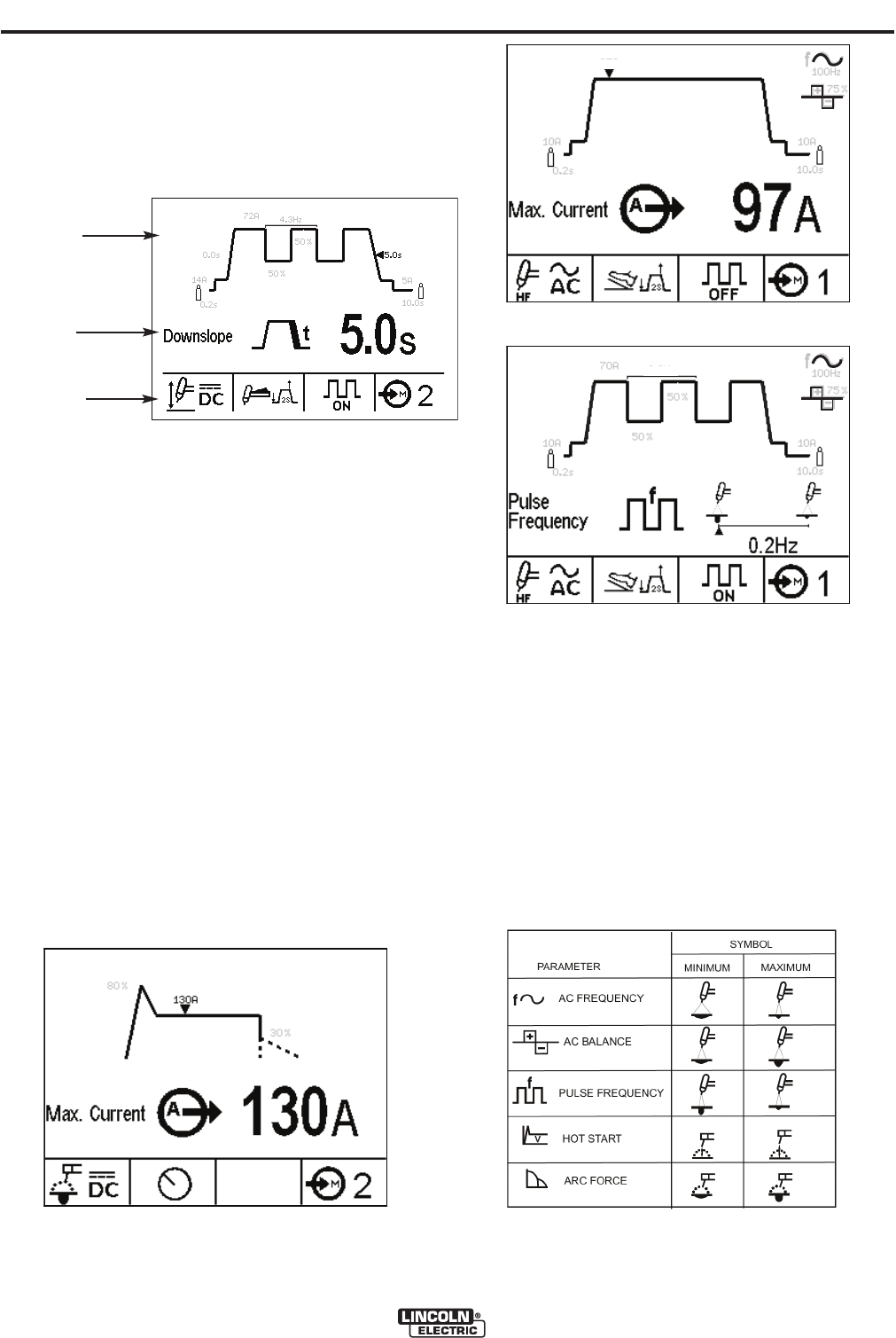
1. The Weld Sequence Diagram shows the various
parameters that can be selected and adjusted and
their preset values. As the push button/rotary
encoder is pressed a triangular shaped flashing
indicator will highlight the adjustable parameter on
the sequence diagram in bold. Each press of the
encoder will scroll to the next selected parameter
sequentially. Rotating the push button encoder will
change the selected parameter value. The display
is dynamic in that adjusting the selected parameter
dynamically changes the shape of the sequence
diagram. After 5 seconds of inactivity the selected
parameter will default back to the weld output amps
parameter. Depressing the button again will
remember the last selected parameter and begin
the sequential scroll from that parameter.
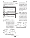
Three Sequence Diagram types exist:
• STICK (See Figure B.4a)
• TIG (See Figure B.4b)
• Pulse TIG (See Figure B.4c)
2. The Parameter Display Section shows the select-
ed parameter its display icon and preset value. To
change the value, rotate the push button/rotary
encoder. Some parameters like AC Frequency have
an Enhanced Icon Display that shows the effect of the
varying parameter on the arc and/or weld bead profile.
As these parameters are adjusted an indicator will
move between the minimum and maximum icon to
show the relative effect of that parameter. Pulse
Frequency shown in Figure B.4c is an example of the
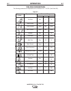
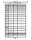
enhanced icon display. Refer to Table B.1 for a list of
Enhanced Icons.
INVERTEC® V311-T AC/DC TIG
0
.0s
0.2s
1
4A
7
2A
4
.3Hz
5
0%
5
0%
5
.0s
5A
1
0.0s
1. Weld Sequence
Diagram
2. Parameter
Display
3. Mode Push Button
Indicators
80%
30%
1
0A
10A
100Hz
10.0s
0.2s
f
+
-
75%
97A
10A
100Hz
10.0s
0.2s
f
+
-
75%
70A
50%
50%
10A
0.2Hz
.
.
.
.
.
.
.
.
.
.
.
.
..
.
.
.
.
Figure B.4a
Figure B.4b
Figure B.4c
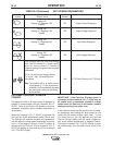
Table B.1