


B-6
OPERATION
B-6
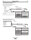
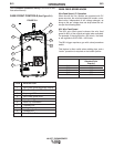
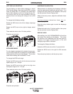
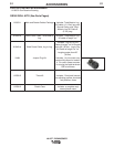
LEFT DISPLAY SELECTION
The left display can show either amperage or actual
WFS during welding. Note that actual WFS is not the
same as preset WFS. For example, the preset WFS
may be set to 400 ipm, but the arc voltage is only 15V.
The actual WFS will be approximately 280 ipm
because there is not enough arc voltage to run at 400
ipm.
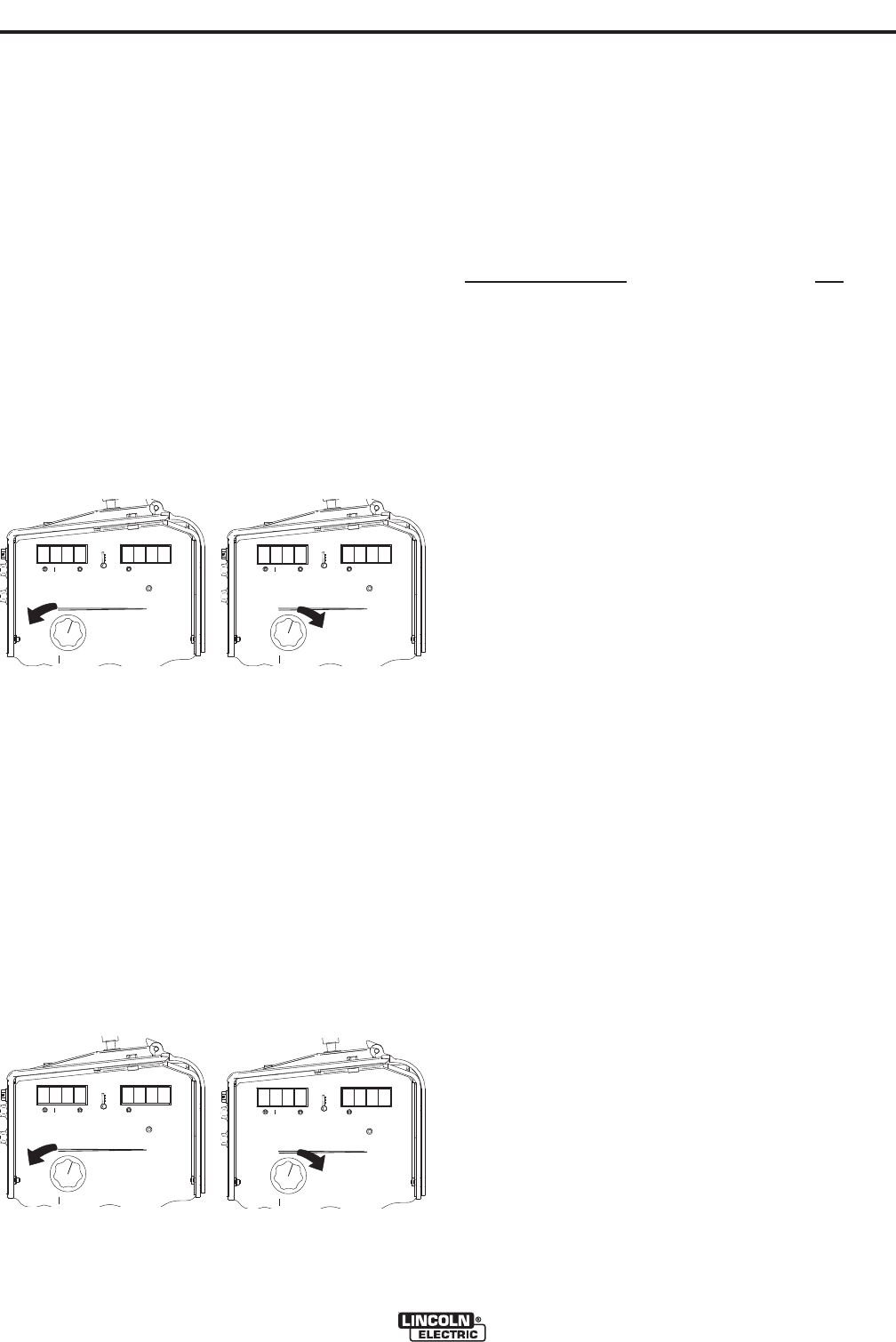
To change the left display reading:
Rotate the WFS knob to the left to display amperage
(current).
Rotate the WFS knob to the right to display actual
WFS.
Then rotate the knob to the 12 oʼclock position.
Press the set-up button.
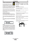
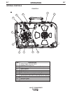
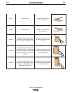
WFS KNOB RANGE
For wire feeders equipped with standard torque gear-
ing, the WFS range can be changed to provide better
knob sensitivity at low wire feed speeds. This is often
useful when welding with Innershield™ wires.
To change the WFS knob range:
Rotate the WFS knob to the left for the low wire feed
speed range of 40 – 405 ipm
Rotate the WFS knob to the right for the high wire
feed speed range of 40 – 715 ipm.
Then rotate the knob to the 12 oʼclock position.
Press the set-up button.
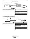
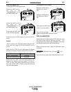
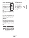
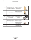
AMPERAGE CALIBRATION
Measurements for adjusting the Amperage calibration
must be made before entering the set-up menu. If no
changes are being made to the calibration, then press
the set-up button to enter Display Hold.
While in the set-up menu, adjust the calibration factor
as follows:
Power Source Amperage 200
Feeder Amperage 210
Press the set-up button again to enter the Amperage
Calibration.
Rotate the knob to the 12 oʼclock position, then press
the set-up button to enter Display Hold.
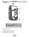
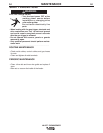
DISPLAY HOLD
After welding, the LN-25 IRONWORKER will hold the
last values from welding on the display. The values
will continue to be displayed until the hold period is
finished, the trigger is pulled again, or the cold
feed/gas purge switch is activated.
To change the Display Hold time:
Rotate the WFS knob to the left for 5 seconds Hold.
Rotate the WFS knob to the right for 300 seconds
Hold.
Press the set-up button to exit the set-up menu.
LN-25™ IRONWORKER
d
c
I
u
r
r
S
P
V
A
OO
OO
WFS
LN™-25 IRONWORKER
S
I
o
P
d
V
A
OO
OOWFS
LN™-25 IRONWORKER
V
A
OO
OO
WFS
E
d
d
E
F
I
S
P
LN™-25 IRONWORKER
S
V
A
OO
OOWFS
H
I
P
d
LN™-25 IRONWORKER
= Calibration Factor Example: = 1.05