


B-2
INSTALLATION
IDEALARC® DC-1000
B-2
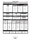
Remote Output Control - (Optional)
The K775 Remote Output Control consists of a control
box with 28 ft. (8.4m) of four conductor cable. This
connects to terminals 75, 76, 77 on the terminal strip,
and the case grounding screw so marked with the
symbol on the machine. These terminals are
made available by opening the terminal access cover
on the left side of the case front. This control will give
the same control as the output control on the
machine.
Mode Switch
The toggle switch labeled C (I) Innershield, CV(S)
Submerged Arc, CC (or Variable Voltage) is used to
select the proper welder characteristics for the
process being used. The CC (or Variable Voltage)
mode is primarily available for use with older wire
feeding equipment such as the LAF-3, LT-34 and so
forth. Use of this type of older equipment requires the
addition of an NL Option Kit.
SET-UP FOR VARIOUS PROCEDURES
1. Selection of mode switch position - There are
several general rules to follow in the selection of
the mode switch position.
a. Use the CV(I) mode for all FCAW and GMAW
processes. The CV(I) mode is also used for
air carbon arc using carbon rods up to and
including 5/8” (15.9mm) dia.
Welding with NR®-151, 202, 203 and other
electrodes below 20 volts, is not recommend-
ed.
b. Use the CV(S) mode for all submerged arc
welding. This applies to both low and high
travel speeds.
c. The CC (Variable Voltage) mode is available
for high current large puddle submerged arc
procedures that cannot be done as well with
the constant voltage mode. CC mode should
be used for 3/16” (4.8mm) diameter electrode
and above where high current surges cause
machine shutdown when starting. This occurs
primarily when the slag ball is not cut from the
electrode prior to starting. (Also requires a
wire feeder that has a constant current mode
- i.e. NA-3S).
NOTE: Some processes and procedures may be bet-
ter with the mode switch in the other CV position. If
the mode switch position initially selected is not pro-
ducing the desired results, then place the mode switch
in the other CV position and make a test weld. Then
use the CV mode switch position that gives the
desired results.
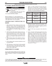
2. NA-3 - The NA-3 should be set for the mode being
used on the power source. If using either of the
CV modes, the NA-3 CC board switch should be
set for CV. If the power source is used in the CC
mode, then the NA-3 CC board mode switch
should be placed in the CC position.
All the NA-3’s when used with the DC-1000 are capa-
ble of cold starting with the constant current board
mode switch in CC. Cold starting permits the wire to
be inched down to the work, automatically stop, and
automatically energize the flux hopper valve. All NA-
3’s made after September, 1976 are capable of cold
starting on either CV or CC settings of the constant
current board.
On the NA-3, set the open circuit voltage control to the
same dial setting as the arc voltage control. If the pro-
cedure has not yet been established, a good starting
point is to set the OCV to #6.
Run a test weld, setting the proper current, voltage
and travel speed. Once the proper welding procedure
is established and if the start is poor - wire blast off,
stub, etc. - adjust the NA-3 OCV and inch speed con-
trols for optimum starting. In general, a low inch speed
and an OCV dial setting identical to the voltage dial
setting will provide the best starting.
To further optimize starting, adjust the OCV by making
repeated starts and observing the NA-3 voltmeter
action. With proper adjustment of the OCV control, the
voltmeter needle will swing smoothly up to the desired
arc voltage and thus provide repeatable starts.
If the voltmeter swings above the set voltage and then
back to the desired welding voltage, the OCV setting
is too high. This usually results in a bad start where
the wire tends to “blast off”.
If the voltmeter needle hesitates before coming up to
the desired voltage, the OCV is set too low. This will
cause the electrode to stub.