


F-3
DIAGRAMS
F-3
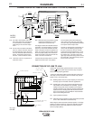
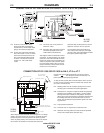
IDEALARC® DC-1000
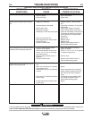
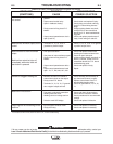
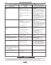
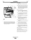
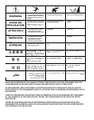
CONNECTION OF DC-1000 to NA-5
N.A. Welding cables must be of proper capacity for the cur-
rent and duty cycle of immediate and future applica-
tions.
N.B. Extend lead 21 using #14 or larger insulated wire phys-
ically suitable for the installation. An S16586-[ ] remote
voltage sensing work lead is available for this purpose.
Connect it directly to the work piece keeping it separate
from the welding work cable connection to work piece.
For convenience, this extended #21 lead should be
taped along the welding work cable.
N.C. Tape up bolted connection.
N.D. Connect the NA-5 control cable ground lead to the
frame terminal marked near the power source ter-
minal strip. The power source must be properly ground-
ed.
N.E. If using an older automatic control cable with leads 75,
76, 77: Connect lead 75 to #75 on terminal strip, con-
nect lead #76 to #74 on terminal strip, connect lead
#77 to #73 on terminal strip.
N.F. Connect the jumpers on the NA-5 voltage board as fol-
lows: Connect RED jumper to pin “S”, Connect WHITE
jumper to pin “B”.
N.G. Set the DC-1000 or DC-1500 controls as follows: Set
the control switch to “Output Control Remote”. For
Submerged Arc Processes set the switch to “C.V.
Submerged Arc”. For Open Arc Processes, set the
mode switch to “C.V. Innershield”.
N.H. For proper operation, the electrode cable must be
snugged under the clamp bar on the left side of the NA-
5 control box.
N.J. Terminals #73 and #74 were not present on DC-1500
machines below code 8294. These earlier code
machines are not suitable for use with the NA-5.
N.K. Alternative 500 amp positive terminal connection pro-
vided on DC-1000 models above code 9500 only.
N.L. Alternate submerged arc mode available for improved
arc stability in high current, large puddle, slow travel
procedures by making special connections on both DC-
1500 and NA-5.
On DC-1500 Control Board (G1530-2 and superseding)
remove red and blue jumpers from “FR” pins and reconnect
to corresponding “SR” pins.
On NA-5 Voltage Board (G1556-1 and superseding) white
jumper must be connected to pin “D”.
NA-5 pin “D” connection may also be used for some proce-
dures on DC-1500 without control board jumpers, DC-1500
with control board jumpers on “FR” pins or DC-1000.
Above diagram shows electrode connected positive. To change
polarity turn power off, reverse the electrode and work leads at
the power source, position the positive - negative switch on the
power source to correspond to the polarity of the electrode cable
connection. Refer to NA-5 operating manual for required NA-5
control box polarity connections.
2
1
42
3
1
3
2
7
3
7
4
7
5
7
6
7
7
4
G ND
N
E
G
A
TIVE
POSITIVE
2
1
N
.
A.
C
O
N
TR
O
L
C
A
BLE
3
2
3
1
2
C
B
A
}
}
T
O
N
A-
5
I
N
P
U
T
C
ABL
E
PLU
G
N
.
J.
N
.
F.
N
.
F
.
N
.
E
.
N
.
K.
CONTACT ASSEM
B
LY
F
ROM
NA-5 W
I
R
E
N
.B
.
&
N.
C.
BOL
T
TO CAB
L
E
S
N
.
D
.
CONNECT TO WORK
N
.C.
&
N
.
H
.
S16889
8-2-90F