


A-3
INSTALLATION
WELD-PAK 100
SELECT SUITABLE LOCATION
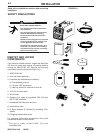
Locate the welder in a dry location where there is free
circulation of clean air into the louvers in the back and
out the front of the unit. A location that minimizes the
amount of smoke and dirt drawn into the rear louvers
reduces the chance of dirt accumulation that can block
air passages and cause overheating.
STACKING
WELD-PAK 100ʼs cannot be stacked.
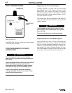
TILTING
Each machine must be placed on a secure, level sur-
face, either directly or on a recommended undercar-
riage. The machine may topple over if this procedure
is not followed.
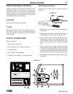
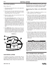
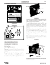
OUTPUT CONNECTIONS
Refer to Figure A.2.
1. Work Cable Access Hole.
2. Gun Cable and Control Lead Access Hole.
3. Connector Block.
4. Gun Trigger Lead Connectors.
5. Positive (+) and negative (–) output terminals.
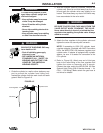
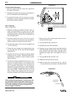
Work Clamp Installation
Attach the work clamp per the following: Refer to
Figure A-3.
FIGURE A.3
WELD-PAK 100
WELD-PAK 100
4
5
8
3 6
7
1
2
+
-
1. Remove the screw, pressure plate and backing nut
from clamp.
2. Remove plastic handle from same side of clamp by
pulling steadily on handle until it slides off clamp.
3. Insert the work cable terminal lug with the larger
hole through the hole in the end of the plastic han-
dle. Slide plastic handle several inches further onto
cable to allow easy and clear access to terminal
lug.
4. Secure work cable to clamp by inserting screw
through hole in clamp, attaching cable lug on inside
of clamp, and installing pressure plate and backing
nut. make sure pressure plate is installed such that
it prevents nut from turning. tighten screw securely.
5. Slide plastic handle back onto clamp and into origi-
nal position.
FIGURE A.2
SCREW
SCREW
PLASTIC HANDLE
PLASTIC HANDLE
WORK CABLE
WORK CABLE
BACKING PLATE & NUT
BACKING PLATE & NUT