


Failure to follow these instructions can cause immedi-
ate failure of components within the welder.
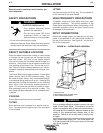
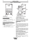
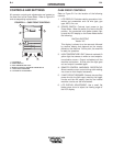
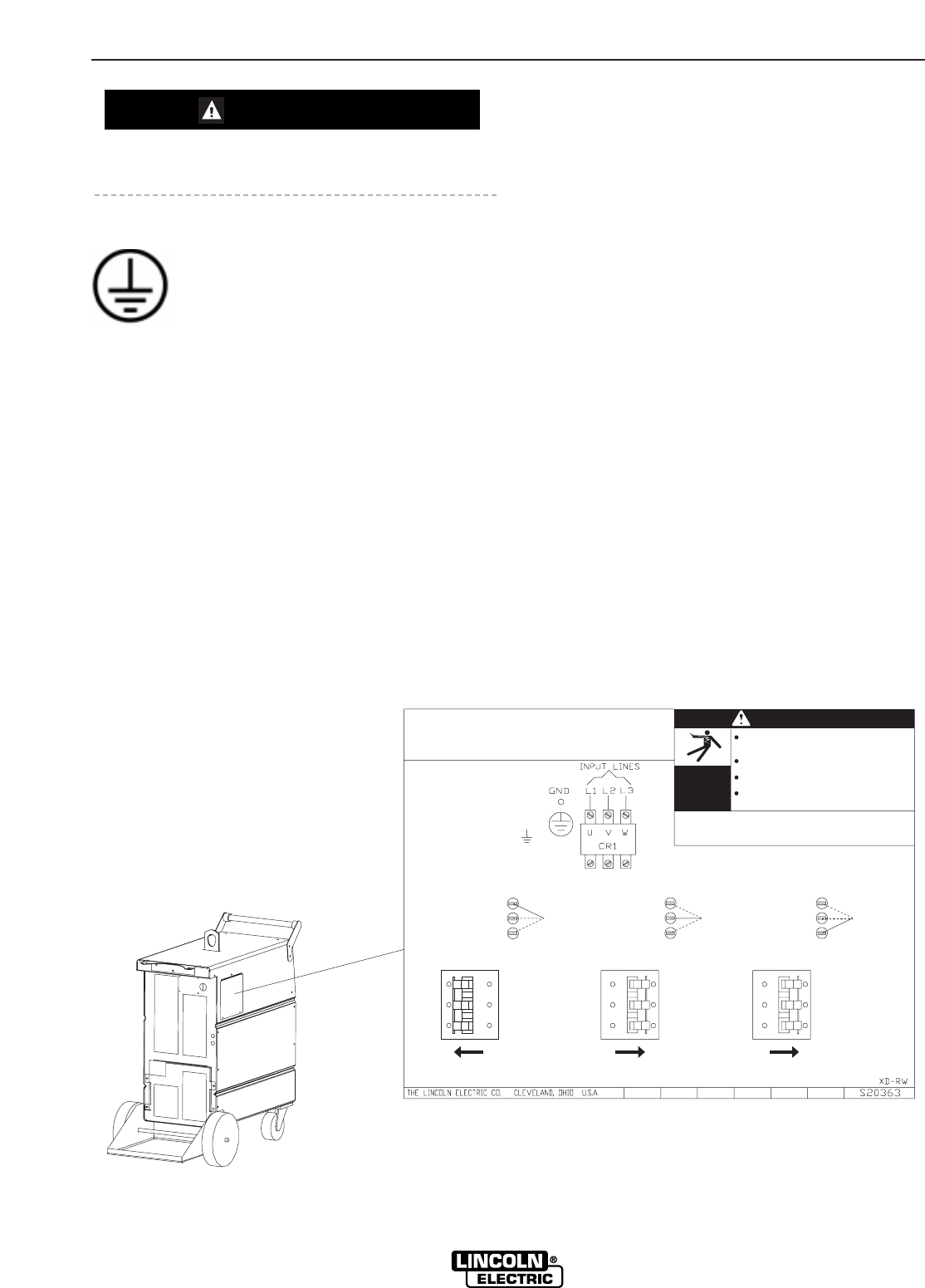
GROUND CONNECTIONS
The frame of the welder must be grounded.
A ground terminal marked with the symbol
is located inside the reconnect/input
access door for this purpose. See your
local and national electrical codes for proper ground-
ing methods. See Figure A.2 for the location of the
reconnect/input access door and related connection
diagram.
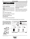
INPUT POWER CONNECTIONS
Connect L1, L2, L3 according to the Input Supply
Connection Diagram decal located on the reconnect/-
input access door. See Figure A.2.
INPUT FUSE AND SUPPLY WIRE
CONSIDERATIONS
Refer to the Technical Specifications at the beginning
of this Installation section for recommended fuse and
wire sizes. Fuse the input circuit with the recom-
mended super lag fuses or delay type circuit breakers.
Choose an input and grounding wire size according to
local or national electrical codes. Using fuses or cir-
cuit breakers smaller than recommended may result in
“nuisance” shut-offs from welder inrush currents, even
if the machine is not being used at high currents.
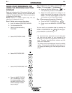
INPUT VOLTAGE RECONNECT
PROCEDURE
Welders are shipped connected for the highest input
voltage listed on the rating plate. To change this con-
nection for a different input voltage, refer to reconnect
instructions in Figure A.2 and proceed according to
the steps that follow for the appropriate voltage.
INSTALLATION
A-3 A-3
POWER WAVE 450
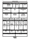
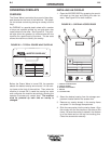
FIGURE A.2 - CONNECTION DIAGRAM ON RECONNECT/INPUT ACCESS DOOR
VOLTAGE=208-230V
4. POSITION SWITCH TO DESIRED INPUT VOLTAGERANGE.
3. CONNECT LEAD "A"TO DESIREDINPUT VOLTAGERANGE.
2. CONNECT LEAD MARKED
1. CONNECT L1, L2, &L3 INPUT
INPUT SUPPLY CONNECTION DIAGRAM
NOTE:
MACHINES ARE SHIPPED FROM FACTORY
CONNECTED FOR 440 (OR 460) VOLTS
TO GROUNDPER NATIONAL
SUPPLY LINES TO THE INPUT
ELECTRICAL CODE.
SIDE OF CR1CONTACTOR AS
SHOWN.
IF MACHINE CEASESTO OPERATE(NO METER, NO FAN)
AND THERE ISNO OTHER KNOWNFAILURE: CHECK FUSE;
REPLACE WITH A 5AMP SLOW BLOW ONLY.
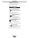
Disconnect inputpower before inspecting
or servicingmachine.
Do not operate with covers removed.
Do not touchelectrically live parts.
Only qualified persons should install,use
or servicethis equipment.
208-230V
380-415V
440-460V
208-230V
380-415V
440-460V
208-230V
380-415V
440-460V
"A" "A" "A"
VOLTAGE=380-415V VOLTAGE=440-460V
WARNING
ELECTRIC
SHOCK
CAN KILL
Also called “inverse time” or “thermal/magnetic” circuit breakers. These breakers have a delay in tripping action that decreases as the mag-
nitude of the current increases.
NOTE: Turn main input power to
mthe machine OFF before perform-
ing reconnect procedure. Failure to
do so will result in damage to the
machine. DO NOT switch the re-
connect bar with machine power
ON.
CAUTION