


A-7
INSTALLATION
DC-655
A-7
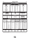
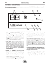
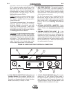
TERMINAL STRIPS
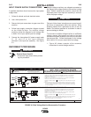
Terminal strips are available behind the cover panel
on the lower case front to connect wire feeder control
cables that do not have a 14 Pin MS-type connector.
Refer to figure A.3 for the location of this cover panel.
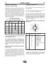
These terminals supply the connections as shown in
the following Terminal Strip charts. See Auxiliary
Power Table for rating of circuit breaker in 115VAC
circuit. Remove a plug button from the terminal strip
cover and install an appropriate strain relief clamp for
the cable being used. NOTE: There are two work
sense lead connection points on the terminal strip.
Connect both the work sense lead #21 from the 14 pin
connector and #21 lead of the control cable to “-21”
when welding positive polarity or to “+21” when weld-
ing negative polarity.
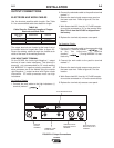
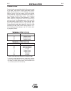
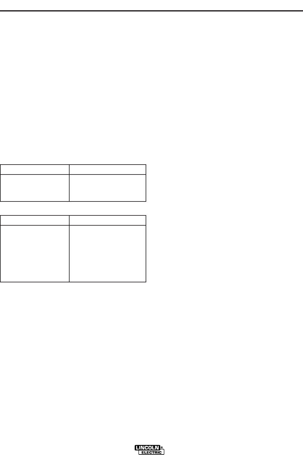
TERMINAL STRIP 1 (T.S.1)
TERMINAL STRIP 2 (T.S.2)
Lead No. Function
75 Output Control
76 Output Control
77 Output Control
1.
115VAC circuit is also present on IEC 974-1 European models.
2.
If connecting a feeder cable directly to the terminal strip, Lead #21
from the cable is connected to “-21” on the terminal strip for posi-
tive welding. If welding negative polarity, connect lead #21 to the
“+21” connection point on the terminal strip.
Lead No. Function
+21 Work Connection
-21 Work Connection
2
41 42 VAC
4 Trigger Circuit
2 Trigger Circuit
31 115 VAC
1
32 115 VAC
1