


B-6
OPERATION
B-6
1. Current Control - This knob is used to set
the welding current from 5 to 315 amps. Read the
complete Operating Instructions section for more
information on Local and Remote setting of current.
2. AC Wave Balance Control - This knob is
active in the AC TIG mode only. It is used to set the
amount of cleaning and/or penetration produced
during an AC TIG weld. Auto Balance™ automati-
cally sets the AC Wave balance according to the
welding current. If manual adjustment is desired,
the balance can be adjusted from +0 (maximum
cleaning) to +10 (maximum penetration).
Read the Advanced Features section for a com-
plete explanation of the AC Wave Balance.
3. Post Flow Time Control - This knob is active
in the TIG mode only. It adjusts the post flow time
from 5 to 50 seconds for shielding gas. It also
adjusts cooling water flow when the optional
K1621-1 Water Solenoid Kit is used.
4. Down Slope Time Control - This knob is
active in 4-Step TIG mode only. It adjusts the time
(from 0.5 to 10 seconds) the welding output takes to
ramp down from the preset level to 25% ±10% of
that level.
5. Mode Switch - A three position toggle switch used
to select the welding mode. Refer to the WELDING
OPERATION section for more information on how
the machine functions in each of the following
modes:
Stick: This mode is used for the stick electrode
(SMAW) welding process. In this position the only
active control is the output current control. The output
terminals are continuously energized.
2-Step TIG: This mode is used for the TIG (GTAW)
welding process. An Arc Start switch must be used to
weld. The Down Slope Time has no effect in this mode.
4-Step TIG: This mode is used for the TIG (GTAW)
welding process. An Arc Start switch must be used to
weld. All controls are active in this mode.
SQUARE WAVE TIG 275
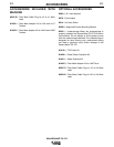
CONTROLS AND SETTINGS
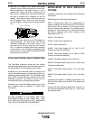
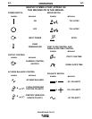
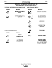
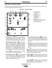
All operator controls and adjustments are located on the case front of the Square Wave TIG 275. Refer to Figure
B.1 and corresponding explanations following.
FIGURE B.1 - CONTROL PANEL
10
6
5
78
69
11
12
13
14
15
1
2
3
4
1. Output Control Knob
2. AC Wave Balance Knob
3. Post Flow Knob
4. Down Slope Time Knob
5. Mode Switch
6. Trimmer Potentiometer
7. Digital Ammeter
8. Digital Voltmeter
9. Thermal Protection Light
10. Power Switch
11. Polarity Switch
12. Electrode Connection (Twist-Mate Connector)
13. Work Connection (Twist-Mate Connector)
14. Remote Control Amphenol
15. Water Solenoid (Optional)
A
2