


B-8
OPERATION
B-8
SQUARE WAVE TIG 275
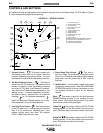
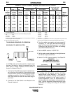
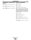
(1) When used with argon gas. The current ranges shown must be reduced when using argon/helium or
pure helium shielding gasses.
(2) Tungsten electrodes are classified as follows by the American Welding Society (AWS):
Pure ...............EWP
1% Thoriated . .......EWTh-1
2% Thoriated . .......EWTh-2
Though not yet recognized by the AWS, Ceriated Tungsten is now widely accepted as a substitute for
2% Thoriated Tungsten in AC and DC applications.
(3) DCEP is not commonly used in these sizes.
(4) TIG torch nozzle “sizes”are in multiples of 1/16ths of an inch:
#4 = 1/4 in. (6 mm)
#5 = 5/16 in. (8 mm)
#6 = 3/8 in. (10 mm)
#7 = 7/16 in. (11 mm)
#8 = 1/2 in. (12.5 mm)
#10 = 5/8 in. (16 mm)
(5)
TIG torch nozzles are typically made from alumina ceramic. Special applications may require lava nozzles,
which are less prone to breakage, but cannot withstand high temperatures and high duty cycles.
TABLE B.1 TYPICAL CURRENT RANGES FOR TUNGSTEN ELECTRODES
(2)
.010 (.25)
0.020 (.50)
0.040 (1.0)
1/16 (1.6)
3/32 (2.4)
1/8 (3.2)
5/32 (4.0)
3/16 (4.8)
1/4 (6.4)
2-15
5-20
15-80
70-150
150-250
250-400
400-500
500-750
750-1000
(3)
(3)
(3)
10-20
15-30
25-40
40-55
55-80
80-125
2-15
5-15
10-60
50-100
100-160
150-210
200-275
250-350
325-450
2-15
5-20
15-80
70-150
140-235
225-325
300-400
400-500
500-630
2-15
10-20
20-30
30-80
60-130
100-180
100-240
190-300
250-400
---
5-20
20-60
60-120
100-180
160-250
200-320
290-390
340-525
3-8 (2-4)
5-10 (3-5)
5-10 (3-5)
5-10 (3-5)
13-17 (6-8)
15-23 (7-11)
21-25 (10-12)
23-27 (11-13)
28-32 (13-15)
3-8 (2-4)
5-10 (3-5)
5-10 (3-5)
9-13 (4-6)
11-15 (5-7)
11-15 (5-7)
13-17 (6-8)
18-22 (8-10)
23-27(11-13)
#4, #5, #6
#5, #6
#6, #7, #8
#8, #10
1%, 2%
Thoriated
Tungsten
1%, 2%
Thoriated
Tungsten
Pure
Tungsten
1%, 2%
Thoriated
Tungsten
Zirconiated
Pure
Tungsten
1%, 2%
Thoriated
Tungsten
Zirconiated Aluminum
Stainless
Steel
Tungsten
Electrode
Diameter
in. (mm)
TIG Torch
Nozzle
Size
(4)
,
(5)
DCEN (
-
) DCEP (
+
)
Unbalanced Wave Balanced Wave
AC Approximate Argon
Gas Flow Rate
C.F.H. (1/min.)
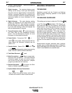
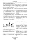
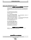
TIG WELDING SEQUENCE OF OPERATION
WELDING IN TIG MODE (2-STEP)
In 2-STEP mode an Arc Start switch or Amptrol must
be used. The switch or Amptrol is pressed to start the
weld. (Step 1) Output continues until the switch or
Amptrol is released. (Step 2)
1. Connect the Twist Mate plug to the receptacle locat-
ed on the front of the machine.The connection locks
into place with a quarter turn making both the power
and gas connections. See the TIG TORCH CON-
NECTION section to install the Twist Mate plug on
your torch.
2. Connect an Arc Start Switch or an Amptrol to the
Remote Amphenol.
3. Turn the welder, gas supply and water supply (if
equipped), on. The digital ammeter/voltmeter dis-
plays will illuminate when the power is on. NOTE:
Cooling fan may not be “ON” when not welding.
(See MAINTENANCE Section)
4. Set the MODE switch to “2-STEP TIG”.
5. Set the peak current displayed on the digital amme-
ter with the output control knob.
6. Select AC or DC- electrode polarity. See Table B.2.
7. If welding with AC polarity, set the AC Wave
Balance Knob to Auto Balance™. This gives the
optimum ratio between cleaning and penetration,
automatically adjusted for the output current. If
manual adjustment of the AC Wave Balance is
desired, adjust the wave balance to the desired set-
tings. See the Advanced Features section for more
information on setting and using the AC Wave
Balance.
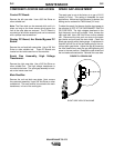
TABLE B.2
RECOMMENDED POLARITY
SETTINGS FOR TIG WELDING
Type of Welding
Electrode
Polarity
Stainless Steel
Aluminum & Magnesium
Other Metals
DC-
AC
DC-
PRESS
(STEP #1)
PREFLOW
(0.5 sec FIXED)
OPTIONAL
TIG PULSER
RELEASE
(STEP #2)
PRESET CURRENT
POSTFLOW
(0.5 to 10 sec. ADJUSTABLE