


A-7
INSTALLATION
POWER FEED 11
A-7
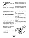
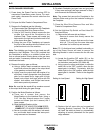
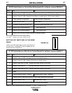
SETTING DIP SWITCHES IN THE WIRE
DRIVE
There is one DIP switch bank on the control board of
the wire drive. It’s labeled S1 and is located and ori-
ented as shown in Figure A.4.
FIGURE A.4
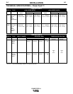
S2 DIP Switch Bank on Control Box Motherboard (For software version S24456-1)
Switch Off On
1 Network Group ID, MSB (Assigns Control Box to a specific group) (Off is factory setting)
2 Network Group ID, LSB (Assigns Control Box to a specific group ) (Off is factory setting)
3 4-Step Domestic Configuration 4-Step European Configuration
4 Power Feed 10 / Dual Power Feed 11
5 Procedure change with trigger “OFF” Procedure change with trigger “ON”
6 Must be off for normal operation Adjust lower limits
7 Must be off for normal operation Adjust upper limits
8 Must be on for all units (Permits selection of extended modes)
Note: the factory shipped settings for Switch S2 are as follows:
PF-11 European - Switches 1,2 & 5-7 “OFF”; Switches 3,4,8 “ON”
PF-11 World - Switches 1-3 & 5-7 “OFF”; Switches 4, 8 “ON”
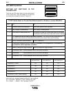
S1 DIP Switch Bank on Wire Drive Control Board (For software version S24468-1)
Switch Off On
1 Network Group ID, MSB (Assigns Wire Drive to a specific group)
2 Network Group ID, LSB (Assigns Wire Drive to a specific group )
3 Network Feed Head ID, MSB (Assigns feed head number to wire drive)
4 Network Feed Head ID (Assigns feed head number to wire drive)
5 Network Feed Head ID, LSB (Assigns feed head number to wire drive)
6 Spare
7 Electrode Sense Polarity = Positive Electrode Sense Polarity = Negative
Switch position must match polarity of weld cable attached to feed plate.
8 Gear Box Ratio = Low Gear Box Ratio = High
Switch position must match actual gear box ratio of wire drive.
Note: the factory shipped settings for Switches 1-7 is “OFF”, Switch 8 is “ON”.
S1
O
N
12345678