


C-2
ACCESSORIES
C-2
DESCRIPTION OF OPTIONAL CON-
TROL BOX PANELS
A number of Optional Features are available for use
with Power Feed 11. Some Installation information is
provided in this section,
REFER TO THE INSTRUC-
TIONS THAT COME WITH EACH KIT FOR DETAILED
INFORMATION REGARDING INSTALLATION.
OPTIONAL PANELS FOR CONTROL BOX
The PF-11 Control Box is designed to accept two con-
trol panels and one door option. Panels can be
mounted in one of two positions: Upper and lower.
Each Control Box is shipped with a Control/Display
(CD) panel installed in the upper position, and a
CV/Gouge (CV/G) panel in the lower position.
The CD panel must be installed in every Control Box.
The remaining panel can be one of the following:
CV/G, MX2, or MSP2.
Note: The CD panel must be installed in the upper
position; its harness is not long enough to allow instal-
lation in the lower position. Similarly, option panels
must be installed in the lower position.
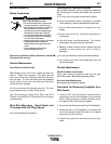
GENERAL PANEL INSTALLATION GUIDELINES:
Installation or removal of any panel can be done with
only a Phillips screwdriver after the system power is
turned off. To remove a panel, remove the two screws
holding it in place, remove the push-on chassis
ground wire and remove the harness connection to
the Control Box main PC board. To install any panel,
reverse that process. Turn power back on when com-
plete (option panels are only recognized at power up.
Do not install panels with the power on.) Note that
removal or installation of any panel may also require
the removal of the other panel, in order to have easy
access to the PC board connectors. Detailed installa-
tion instructions are shipped with each option panel.
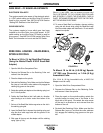
K1542-11 “MX2” Panel
This panel provides a selection of four weld modes:
CV/MIG, CV/Flux Cored, CC/Stick/soft and
CC/Stick/Crisp through a toggle switch and indicator
lights (LEDs). It allows for adjustment of all set up
parameters, Preflow, Run In, Arc Control, Burnback,
Postflow, and Crater, through an up/down toggle
switch, indicator lights and a 3 digit display.
K1542-12 “MSP2” Panel
This panel provides a selection of over 25 weld
modes, including CV, pulse, FCAW and CC, through a
toggle switch and indicator lights (LEDs). It allows for
adjustment of all set up parameters, Preflow, Run In,
Arc Control, Burnback, Postflow, and Crater, through
an up/down toggle switch, indicator lights and a 3 digit
display.
K1640-1 Dual Procedure/ Memory Door Panel
This panel provides two functions: Dual Procedure
and Memory. Dual Procedure provides for setting and
manual selection of two procedures. Selection can be
done at the panel, or through a dual procedure weld-
ing gun switch connected to the Wire Drive trigger
receptacle. Memory provides six independent storage
locations for Control Box settings. All selections are
done with push buttons and indicator lights.
Installation of the door option can be done with only a
Phillips screwdriver and a 3/8” wrench after the sys-
tem power is turned off. Start by removing the upper
panel (for access to the PC board connector) and the
old door (save the hinge parts). Connect the door
option PC board connector and the push-on chassis
ground wire, route the leads through the access hole,
and install the door with the original hinge parts.
Reinstall the upper panel to complete the installation.
Detailed installation instruction are shipped with each
door option.
K1543, K1544 AND K1545 INPUT
CABLE ASSEMBLIES
Available Cable Assemblies:
K1543 - Control cable only. Consists of a 5-conductor
control cable with a 5-pin control cable plug, without
electrode cable, and is available in lengths of 8', 16',
25', 50' and 100'.
K1544 - Consists of a 5-conductor control cable with a
5-pin control cable plug and a 4/0 electrode cable. It is
rated at 600 amps, 60% duty cycle and is available in
lengths of 8', 16', 25', and 50'.
K1545 - Control cable and a 4/0 (85 mm2) electrode
cable with Twist-Mate™ connector on one end and a
stud terminal on the other. It is rated at 500 amps,
60% duty cycle and is available in lengths of 8', 16',
25', and 50'.
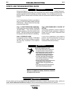
With input power disconnected from the power
source, install the Control Cable Assemblies per the
instruction in INSTALLATION - “Cable Connections”.
POWER FEED 11