


A-9
INSTALLATION
POWER FEED 10 DUAL
A-9
SETTING DIP SWITCHES IN THE WIRE
DRIVE
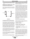
There is one DIP switch bank on each Control PC
board for the wire drives. They are labeled S1 and are
located and oriented as shown in Figure A.4. The PC
board for the left feed head (facing forward) is located
on the rear access panel. The PC board for the right
feed head is located inside on the divider panel.
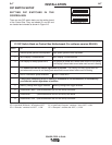
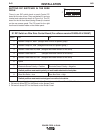
FIGURE A.4
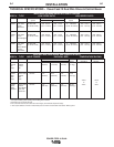
S1 DIP Switch on Wire Drive Control Board (For software version S24029-All & S24467)
Switch Off On
1 Network Group ID, MSB (Assigns Wire Drive to a specific group)
2 Network Group ID, LSB (Assigns Wire Drive to a specific group )
3 Network Feed Head ID, MSB (Assigns feed head number to wire drive)
4 Network Feed Head ID (Assigns feed head number to wire drive)
5 Network Feed Head ID, LSB (Assigns feed head number to wire drive)
6 Spare
7 Electrode Sense Polarity = Positive Electrode Sense Polarity = Negative
Switch position must match polarity of weld cable attached to feed plate.
8 Gear Box Ratio = Low Gear Box Ratio = High
Switch position must match actual gear box ratio of wire drive.
Note: the factory shipped settings for all of the S1 switches on the Power Feed 10 Dual Feeders are:
4 ON and all others OFF for the Board on the Access Panel.
5 ON and all others OFF for the Board on the Divider Panel.
S1
ON
12345678