


B-4
OPERATION
B-4
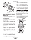
POWER FEED 10 DUAL
The value of the active Set Up parameter, as defined
by the Set Up LED, is displayed on the MX2 panel Set
Up display. The value can be modified with the Set
switch. The Set switch is an up/down center-off
momentary toggle switch. Moving the switch bat up or
down adjusts the displayed value in the correspond-
ing direction. Holding the switch in either direction will
cause the display to move quickly in the correspond-
ing direction until the switch is released, or the upper
or lower parameter limit is reached.
To energize the output studs in either CC/Stick mode,
the right Control/Display panel knob, labeled
Volts/Trim, must be used. The Volts/Trim knob must
be turned clockwise roughly a quarter revolution to
energize the output studs. (The Volts/trim display will
indicate ʻOnʼ when the studs are energized.)
Similarly, turning the knob a quarter turn counter-
clockwise de-energizes the output studs. If a CC/Stick
weld mode is entered through use of the Dual
Procedure, the studs will be in the same state as
when they were last used. If a CC/Stick weld mode
is entered through a Memory recall, the studs will be
de-energized.
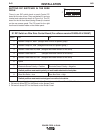
K1542-12 MSP2 Panel:
This panel provides a selection of over 25 weld
modes, including CV, pulse, FCAW and CC, through
a toggle switch and indicator lights (LEDs). It allows
for adjustment of all set up parameters, Preflow, Run
In, Arc Control, Burnback, Postflow, and Crater,
through an up/down toggle switch, indicator lights and
a 3 digit display.
To adjust a set up parameter (Weld Mode being one
of those parameters), first select one of the set up
parameters for adjustment, and then adjust the dis-
played value up or down.
Set up parameters are selected with the Select switch,
an up/down center-off momentary toggle switch.
Moving the switch bat up or down moves an LED in
the corresponding direction. Holding the switch in
either direction will cause the indicator to move quickly
in the corresponding direction until the switch is
released, or the upper or lower limit is reached.
The value of the active set up parameter is shown on
the MSP2 panel digital display. The value can be modi-
fied with the Set switch. The Set switch is an up/down
center-off momentary toggle switch. Moving the switch
bat up or down adjusts the displayed value in the cor-
responding direction. Holding the switch in either direc-
tion will cause the display to move quickly in the corre-
sponding direction until the switch is released, or the
upper or lower parameter limit is reached.
To energize the output studs in either CC/Stick mode,
the right Control/Display panel knob, labeled
Volts/Trim, must be used. The Volts/Trim knob must
be turned clockwise roughly a quarter revolution to
energize the output studs. (The Volts/trim display will
indicate ʻOnʼ when the studs are energized.)
Similarly, turning the knob a quarter turn counter-
clockwise de-energizes the output studs. If a CC/Stick
weld mode is entered through use of the Dual
Procedure, the studs will be in the same state as
when they were last used. If a CC/Stick weld mode is
entered through a Memory recall, the studs will be de-
energized.
CONTROL BOX PANELS -- SET UP
CONTROLS DESCRIPTION
Certain large option panels can modify the set up
parameters Preflow, Run In, Arc Control, Burnback,
Postflow, and Crater. The meaning of those parame-
ters, and their maximum and minimum values, follows.
Preflow - Time delay after the trigger is pulled, but
before weld starts, during which shielding gas flows.
Weld start is defined as the time when both the power
source is energized and the Wire Drive begins feeding
wire. Adjustable from 0.0 (Off) to 2.5 seconds in 0.1s
increments.
Run In - Wire feed speed during arc starting. Wire
Drive will feed wire at the Run In speed for one sec-
ond, or until weld current flows. Low speed gear
range: Off (Run In speed equals weld wire feed
speed) or adjustable from 50 to 150 IPM (1.25 to 3.80
MPM). High speed gear range: Off (Run In speed
equals weld wire feed speed) or adjustable from 75 to
150 IPM (2.00 to 3.80 MPM). NOTE: Run In settings
over 150 IPM produce strange display values used for
troubleshooting and service. If encountered, reset Run
In to 150 IPM or less.
Arc Control - Unitless characteristic, also known as
Inductance or Wave Control. Allows operator to vary
the arc characteristics from “soft” to “harsh” in all weld
modes. Adjustable from -10.0 to 10.0 in increments of
0.1. Off (0.0) is nominal.
Burnback - Time delay after the trigger is released
during which the power source remains energized but
the Wire Drive stops feeding wire. Adjustable from
0.00 (Off) to 0.25 seconds in 0.01 second increments.
Postflow - Time delay after burnback is complete,
during which shielding gas flows. Adjustable from 0.0
(Off) to 10.0 seconds in 0.1 second increments.