


A-2
INSTALLATION
PRO-CUT 25
A-2
Read entire Installation Section before installing the
PRO-CUT 25.
SAFETY PRECAUTIONS
ELECTRIC SHOCK CAN KILL.
• Only qualified personnel
should install this machine.
• Turn the input power OFF
at the disconnect switch or
fuse box and discharge input
capacitors before working
inside the equipment.
• Do not touch electrically hot parts.
• Turn the PRO-CUT Power Switch OFF
when connecting power cord to input
power.
___________________________________________
SELECT PROPER LOCATION
Place the PRO-CUT 25 where clean cool air can
freely circulate in and out the side louvers. Dirt, dust
or any foreign material that can be drawn into the
machine should be kept at a minimum. Failure to
observe these precautions can result in excessive
operating temperatures and nuisance shutdown of the
machine.
A source of clean, dry air or nitrogen must be supplied
to the PRO-CUT 25. Oil in the air is a severe problem
and must be avoided. The supply pressure must be
between 80 and 150 psi. The flow rate is approximate-
ly 4.0 cfm (113 l/min.). Failure to observe these pre-
cautions could result in excessive operating tempera-
tures or damage to the torch.
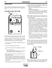
STACKING
The PRO-CUT 25 cannot
be stacked.
TILTING
The PRO-CUT 25 must be placed on a stable, level
surface so it will not topple over.
HIGH FREQUENCY INTERFERENCE
PROTECTION
The PRO-CUT 25 employs a touch start mechanism
for arc initiation which eliminates high frequency emis-
sions from the machine as compared with spark gap
and solid state type high frequency generators. Keep
in mind, though, that these machines may be used in
an environment where other high frequency generat-
ing machines are operating. By taking the following
steps, high frequency interference into the Pro-Cut
can be minimized
(1) Make sure the power supply chassis is connected
to a good earth ground. The work terminal ground
does NOT ground the machine frame.
(2) Keep the work ground clamp isolated from other
work clamps that have high frequency.
(3) If the ground clamp cannot be isolated, then keep
the clamp as far as possible from other work
clamp connections.
(4) When the machine is enclosed in a metal building,
several good earth driven electrical grounds
around the periphery of the building are recom-
mended.
Failure to observe these recommended installation
procedures may cause improper function of the Pro-
Cut or possibly even damage to the control system or
power supply components.
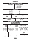
INPUT ELECTRICAL
CONNECTIONS
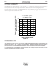
The PRO-CUT 25 is rated for 115VAC or 230VAC
inputs and will automatically reconnect for the sup-
plied voltage. The machine is shipped from the factory
for operation on 115VAC 15 amp circuits. Use on 15
amp branch circuits will limit cutting output as indicat-
ed by the graphics around the output knob. If the out-
put is set at 20 amps or greater, the input fuse or cir-
cuit breaker may “blow” in roughly 30 seconds or less
(depending on fuse or circuit breaker type).
To achieve 20 amp output with 115VAC input, replace
the 15 amp plug on the input cord with the supplied 20
amp plug, and connect the unit to a 20 amp branch
circuit with super lag fuses (or equivalent breaker). To
install the supplied 20 amp plug: Connect the white
(neutral) wire under terminal clamp with silver screw,
and black (hot) wire under terminal clamp with brass
screw. Connect green wire under terminal clamp with
green screw. Tighten terminal wire clamp screws
WARNING