


A-6
INSTALLATION
POWER WAVE 455/R
A-6
ELECTRODE AND WORK CABLE
CONNECTIONS
Connect a work lead of sufficient size and length (Per
Table 1) between the proper output terminal on the
power source and the work. Be sure the connection to
the work makes tight metal-to-metal electrical contact.
To avoid interference problems with other equipment
and to achieve the best possible operation, route all
cables directly to the work or wire feeder. Avoid
excessive lengths and do not coil excess cable. Do
not tightly bundle the electrode and work cables
together.
Use K1796 Coaxial welding cables wherever possible.
(See Section F-5 Connection Diagram).
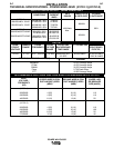
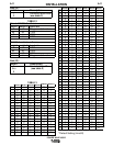
Minimum work and electrode cables sizes are as follows:
TABLE 1
(Current (60% Duty Cycle)
MINIMUM COPPER
WORK CABLE SIZE AWG
Up To-100 Ft. Length (30 m)
400 Amps 2/0 (67 mm2)
500 Amps 3/0 (85 mm2)
600 Amps 3/0 (85 mm2)
NOTE: K1796 coaxial welding cable is recommended
to reduce the cable inductance in long distance Pulse
and STT applications up to 300 amps.
When using an inverter type power source like the
Power Waves, use the largest welding (electrode and
ground) cables that are practical. At least 2/0 copper
wire - even if the average output current would not
normally require it.
When pulsing, the pulse current can reach very
high levels. Voltage drops can become excessive,
leading to poor welding characteristics, if under-
sized welding cables are used.
------------------------------------------------------------------------
Most welding applications run with the electrode being
positive (+). For those applications, connect one end
of the electrode cable to the positive (+) output stud
on the power source (located beneath the spring
loaded output cover near the bottom of the case
front). Connect the other end of the electrode cable to
the wire drive feed plate using the stud, lockwasher,
and nut provided on the wire drive feed plate. The
electrode cable lug must be against the feed plate. Be
sure the connection to the feed plate makes tight
metal-to-metal electrical contact. The electrode cable
should be sized according to the specifications given
in the work cable connections section. Connect a work
lead from the negative (-) power source output stud to
the work piece. The work piece connection must be
firm and secure, especially if pulse welding is planned.
Excessive voltage drops caused by poor work
piece connections often result in unsatisfactory
welding performance.
-------------------------------------------------------------------------
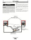
When welding with the STT process, use the positive
output connection labeled (STT) for STT welding. (If
desired, other welding modes can be used on this
stud; however, their average output current will be lim-
ited to 325 amps.) For non-STT processes, use the
positive output connection labeled (Power Wave), so
that the full output range of the machine is available.
Do not connect the STT and Power Wave stud
together. Paralleling the studs will bypass STT cir-
cuitry and severely deteriorate STT welding perfor-
mance. (See Section F-3 Connection Diagram)
-------------------------------------------------------------------------
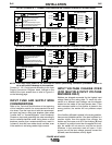
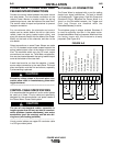
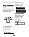
NEGATIVE ELECTRODE POLARITY
When negative electrode polarity is required, such as
in some Innershield applications, reverse the output
connections at the power source (electrode cable to
the negative (-) stud, and work cable to the positive (+)
stud).
When operating with electrode polarity negative the
switch 7 must be set to ON on the Wire Feed Head PC
Board. The default setting of the switch is OFF to rep-
resent positive electrode polarity.
Set the Negative Polarity switch on Wire Feed Head
PC board as follows:
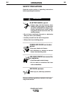
ELECTRIC SHOCK can kill.
• Do not touch electrically live parts or
electrodes with your skin or wet
clothing.
• Insulate yourself from the work and
ground.
• Always wear dry insulating gloves.
------------------------------------------------------------------
1. Turn off power to the power source at the disconnect
switch.
2. Remove the front cover from the power source.
3. The wire feed head board is on the right side of
the power source. Locate the 8-position DIP
switch and look for switch 7 of the DIP switch.
4. Using a pencil or other small object, slide the
switch right to the OFF position for positive
electrode polarity. Conversely, slide the switch
left to the ON position for negative electrode
polarity.
WARNING
O
N
12345678
CAUTION
CAUTION
CAUTION