


B-6
OPERATION
B-6
PULSE WELDING
Pulse welding procedures are set by controlling an
overall "arc length" variable. When pulse welding, the
arc voltage is highly dependent upon the waveform.
The peak current, back ground current, rise time, fall
time and pulse frequency all affect the voltage. The
exact voltage for a given wire feed speed can only be
predicted when all the pulsing waveform parameters
are known. Using a preset voltage becomes
impractical, and instead the arc length is set by
adjusting "trim".
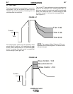
Trim adjusts the arc length and ranges from 0.50 to
1.50, with a nominal value of 1.00. Trim values greater
than 1.00 increase the arc length, while values less
than 1.00 decrease the arc length.
Most pulse welding programs are syngeric. As the
wire feed speed is adjusted, the Power Wave will
automatically recalculate the waveform parameters to
maintain similar arc properties.
POWER WAVE 455/R
The Power Wave utilizes "adaptive control" to
compensate for changes in electrical stick-out while
welding. (Electrical stick-out is the distance from the
contact tip to the work piece.) The Power Wave
waveforms are optimized for a 0.75" (19mm) stick-out.
The adaptive behavior supports a range of stickouts
from 0.50" (13mm) to 1.25" (32mm). At very low or
high wire feed speeds, the adaptive range may be
less due to reaching physical limitations of the welding
process.
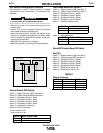
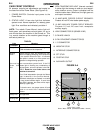
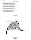
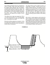
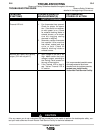
Wave control in pulse programs usually adjusts the
focus or shape of the arc. Wave control values greater
than 0 increase the pulse frequency while decreasing
the background current, resulting in a tight, stiff arc
best for high speed sheet metal welding. Wave control
values less than 0 decrease the pulse frequency while
increasing the background current, for a soft arc good
for out-of-position welding. (See Figure A.6)
Wave Control 0.0
Wave Control +10.0
Wave Control -10.0
FIGURE A.6
Current
Time