


A-4
INSTALLATION
UNDER-COOLER CART
A-4
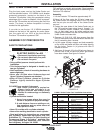
INPUT POWER CONNECTION
Plug the input power cord on the Under-Cooler cart
into the standard bottom 115V NEMA circuit breaker
protected receptacle, located on the back of the
Precision TIG machine. Using this receptacle is taking
advantage of the "cooler as needed" circuit incorporat-
ed into the TIG machine and will prolong the life of the
cooler. The lower, or bottom receptacle is clearly
marked for this application.
If you wish to use the top 115 V NEMA receptacle
located on the back of the machine for cooler opera-
tion, the cooler will run 100% of the time that the
Precision TIG machine is powered "ON".
ASSEMBLY OF PRECISION TIG
SAFETY PRECAUTIONS
• Protect yourself and others from serious injury
ELECTRIC SHOCK Can Kill
• Disconnect input before servicing.
• Do not touch electrically live parts.
• Do not touch live parts
• Only qualified persons should perform this
installation.
• This Undercarriage is designed to handle up to
two gas Cylinders.
• After Installation, check all mounting hardware to
assure tightness.
• Never use Lift Bale when Undercarriage and
Upper Cylinders Supports are attached.
• Keep all Gas Cylinders, placed on Cylinder
Platform, tightly chained to Upper Cylinder
Support!
CYLINDER may explode if damaged.
• Gas under pressure is explosive.
Always keep gas cylinders in an
upright position and always keep
chained to undercarriage or stationary
support.
• Cylinders should be located:
1. Away from areas where they may be
struck or subjected to physical damage.
2. A safe distance from arc welding or cut-
ting operations and any other source of
heat, sparks or flame
• Never lift a welder with a cylinder attached.
• Never allow welding electrode to touch cylinder.
• Read and follow the instructions on compressed
gas cylinders, associated equipment and CGA
publication P-1, “Precautions for Safe Handling of
Compressed Gases in Cylinders,” available from
the Compressed Gas Associate.,1235 Jefferson
Davis Highway, Arlington VA. 22202
Assembly of the Under-Cooler cart to the Precision
TIG machine is actually quite simple. Read carefully
the prior warnings and precautions to assembling to a
Precision TIG machine.
Assembly:
1. Lift the Precision TIG machine approximately 24"
(610mm) off the floor using the lift bale. Lower onto
the Under-Cooler cart aligning holes in the TIG base
with the two pins on each side of the Under-Cooler
cart roof.
2. Fasten the case sides of the Under-Cooler cart to
the TIG machine base using items 4 through 7 in
the 4 locations shown. Washer, lock washer and
nut, (in that order) are to be inside machine base
flange with the head of the bolt on the outside of the
Under-Cooler cart case side.
3. Remove (4) 5/16-18 X .625 long screws from the
front of the machine and discard. Mount handle with
the (4) remaining item 4 screws.
4. Lay the upper cylinder support and hook assembly
on top of the rear baffle and filler rod holder aligning
the top holes. Fasten in (4) places with item 8
screws as shown.
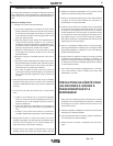
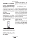
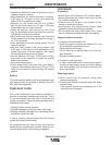
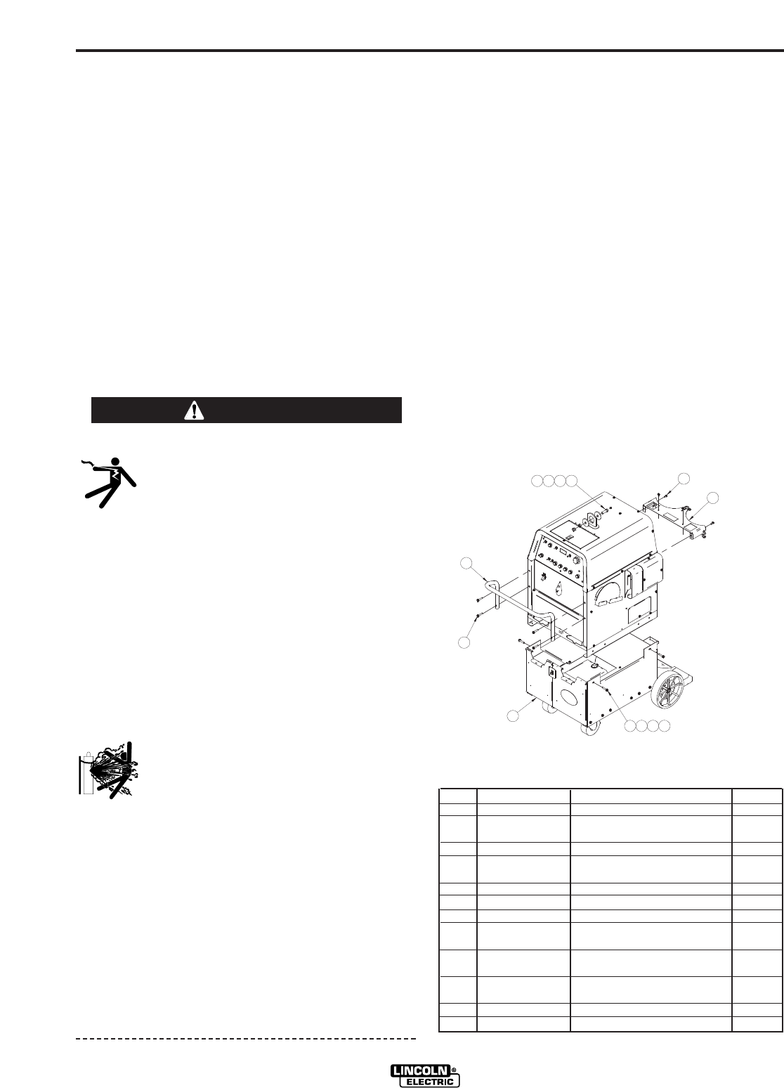
5. Add items 9 through 12 to the lift bale as shown to
prevent use of the lift bale with when gas bottles
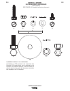
have been loaded. See figure A-2 below.
FIGURE A-2
K1828-1 Under-Cooler Cart: Installation Instructions
Items Part Number Description Req”d
1 G3941 Under-Cooler Cart 1
2 M19767 Upper Cylinder Support 1
and Hook Assembly
3 L11682 Handle 1
4 S9225-47 5/16-18 x 1.50 Thread 8
Forming Screw
5 CF000029 5/16-18 Hex Nut 4
6 E106A-14 5/16 Lock Washer 4
7 S9262-121 5/16 Plain Washer 4
8 S9225-68 1/4-20 x .50 Thread 4
Forming Screw
9 CF000030 1/2-13 x 1.25 Hex Head 1
Cap Screw
10 S9262-62 1/2 Plain Washer 2
(2.25 O.D.)
11 E106A-15 1/2 Lock Washer 1
12 CF000027 1/2-13 Hex Nut 1
WARNING
1
2
3
4
4
5 6 7
8
9101112