


F-1
WIRING DIAGRAM
F-1
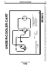
UNDER-COOLER CART
NOTE: This diagram is for reference only. It may not be accurate for all machines covered by this manual. The specific diagram for a particular code is pasted inside
the machine on one of the enclosure panels. If the diagram is illegible, write to the Service Department for a replacement. Give the equipment code number..
M19812
UNDER-COOLER CART
ELECTRICAL SYMBOLS PER E1537
COLOR CODE: B - BLACK OR GRAY
W - WHITE
G - GREEN
G1 -
BASE GROUND CONNECTION
G2 - FAN SHROUD GROUND
CONNECTION
P1 - INPUT POWER PLUG
MTR1 - PUMP MOTOR
MTR2 - FAN MOTOR
W
W
G
W
B
B
B
B
W
1
4
MTR1
MTR2
G2
G1
INPUT: 115 V
50/60 HZ
P1
W
D